
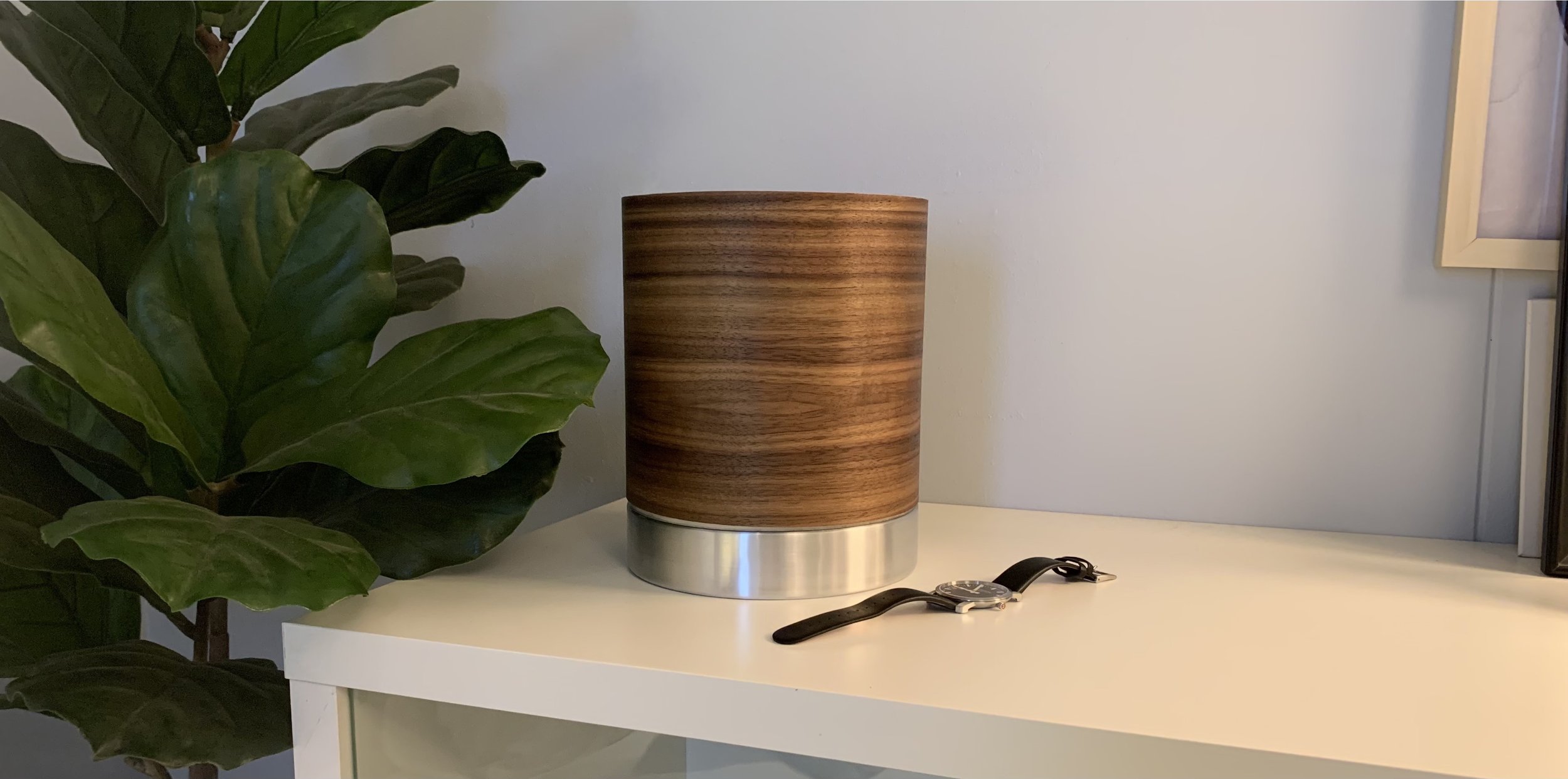
It starts with an ambitious idea
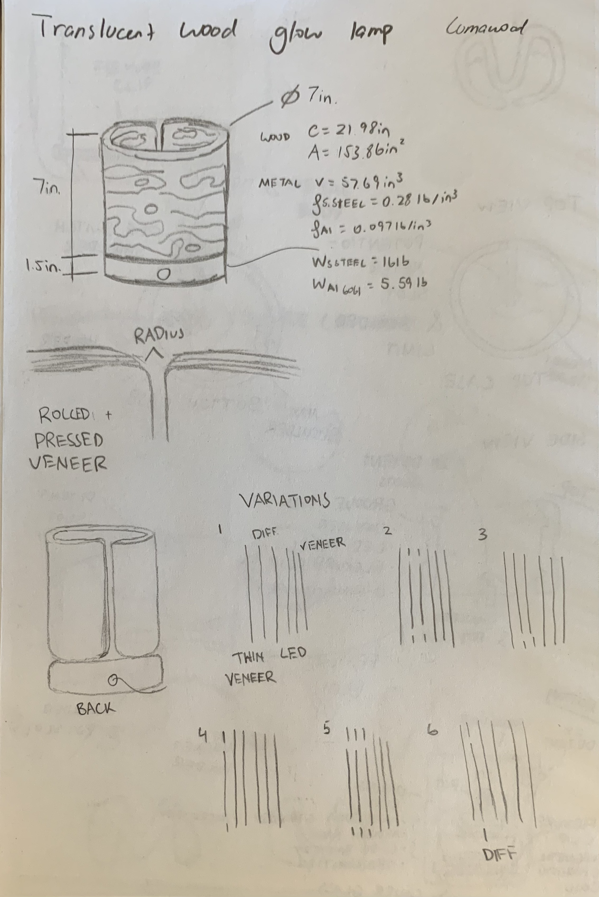
To create a cylindrical lamp that is hollow in the center and perches on top of a solid aluminum band. With translucent wood.
2024

Developing a thought
The idea was to create an ornamental wood lamp that would add a luscious warmth to the room. An extremely thin sheet of wood on the surface will look like solid wood, yet allow light to shine through once it was turned on.
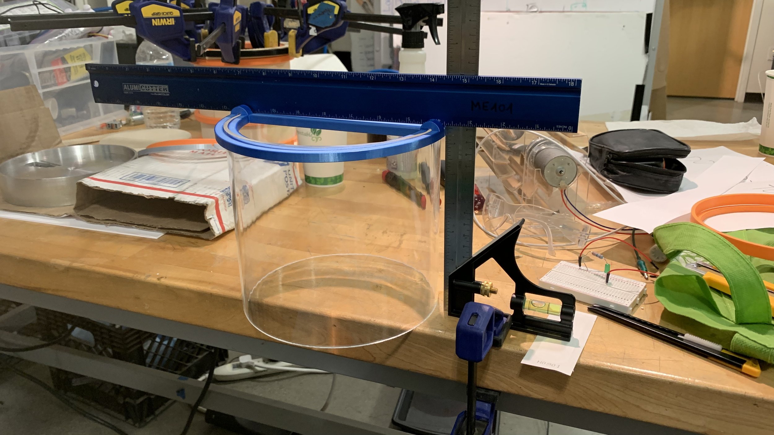
Initially, multiple sheets of veneer would be stacked and vacuum pumped to form a cylinder. For the lighting, LEDs were to be placed radially and shine onto a highly polished internal chamfer, which will then diffuse across a frosted acrylic cylinder.
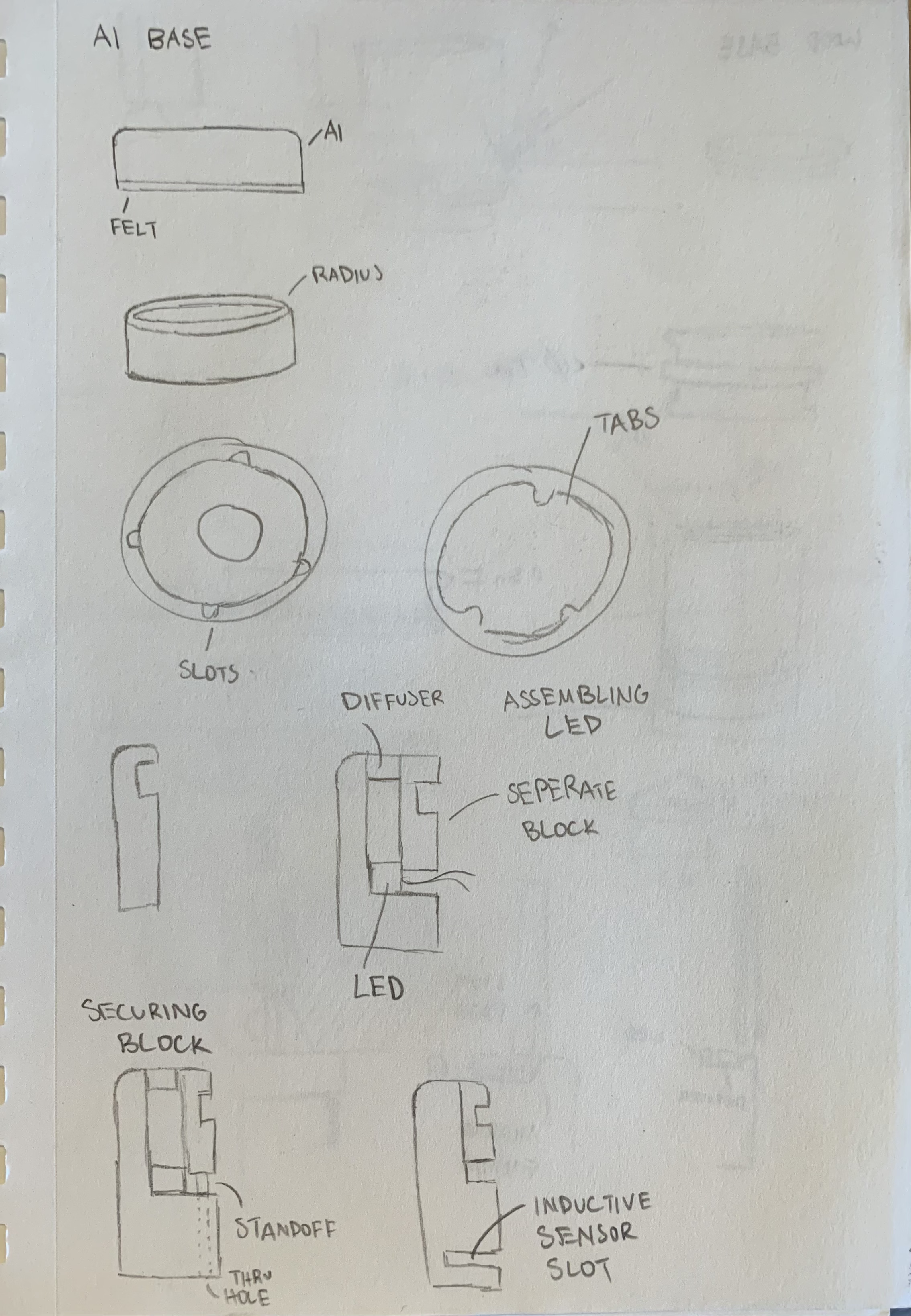
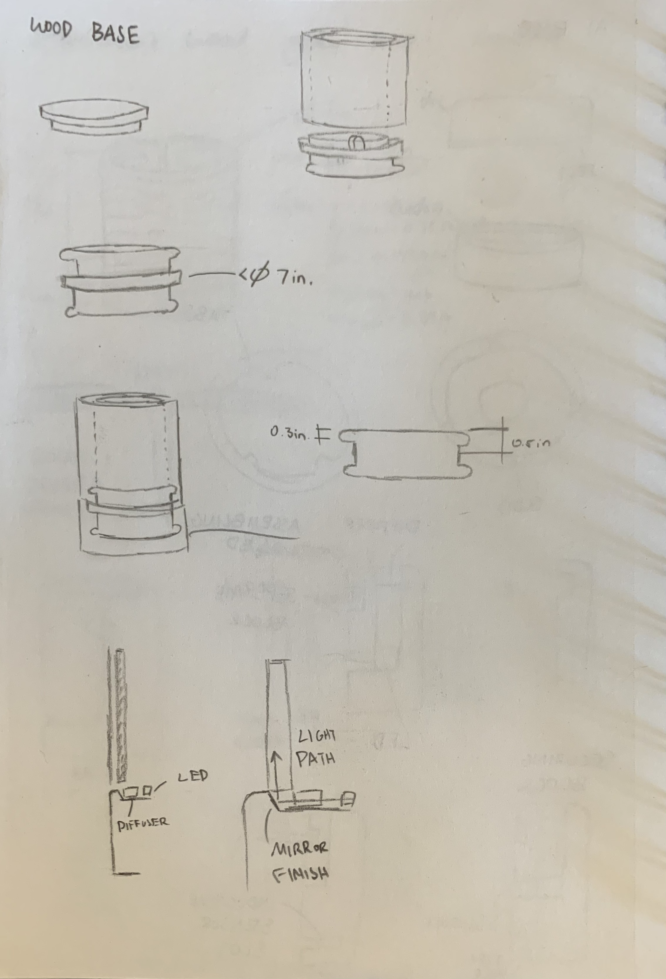
The wood cylinder would lock with a wood base, which would lock with an aluminum base through tabs and rotate through an internal rail.


CAD
This would have been a lot simpler if I took a piece of sheet metal and rolled it up, but that didn’t sit well with me. For a wood lamp to convey warmth, I wanted the body to be wood as well. Essentially the soul of the product.
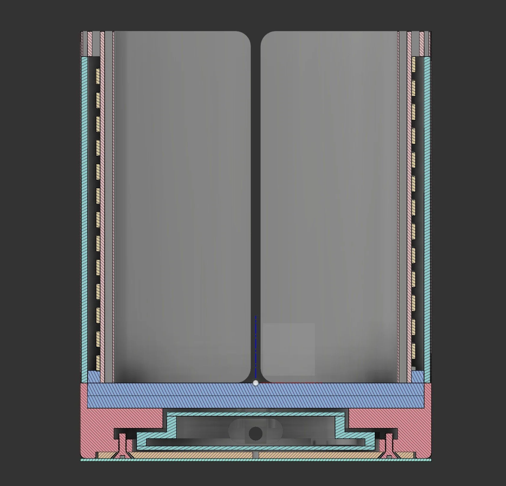
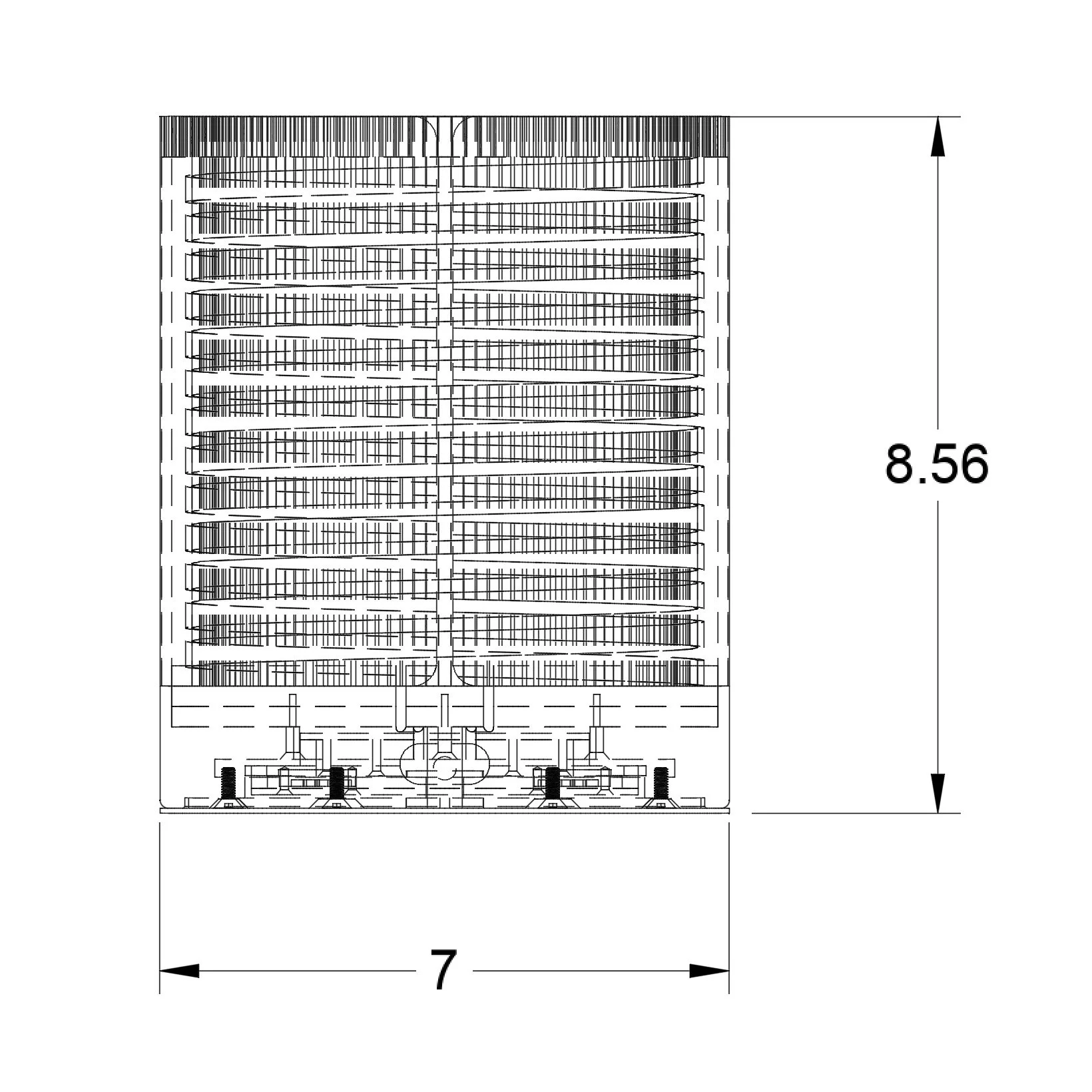
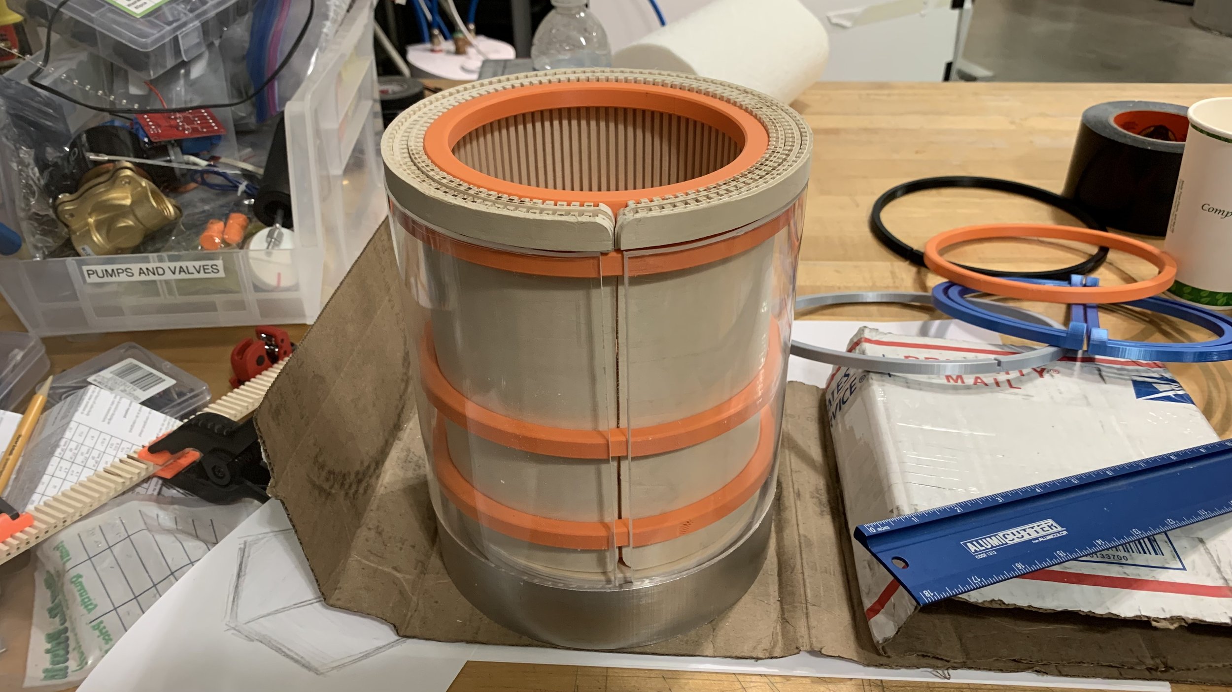
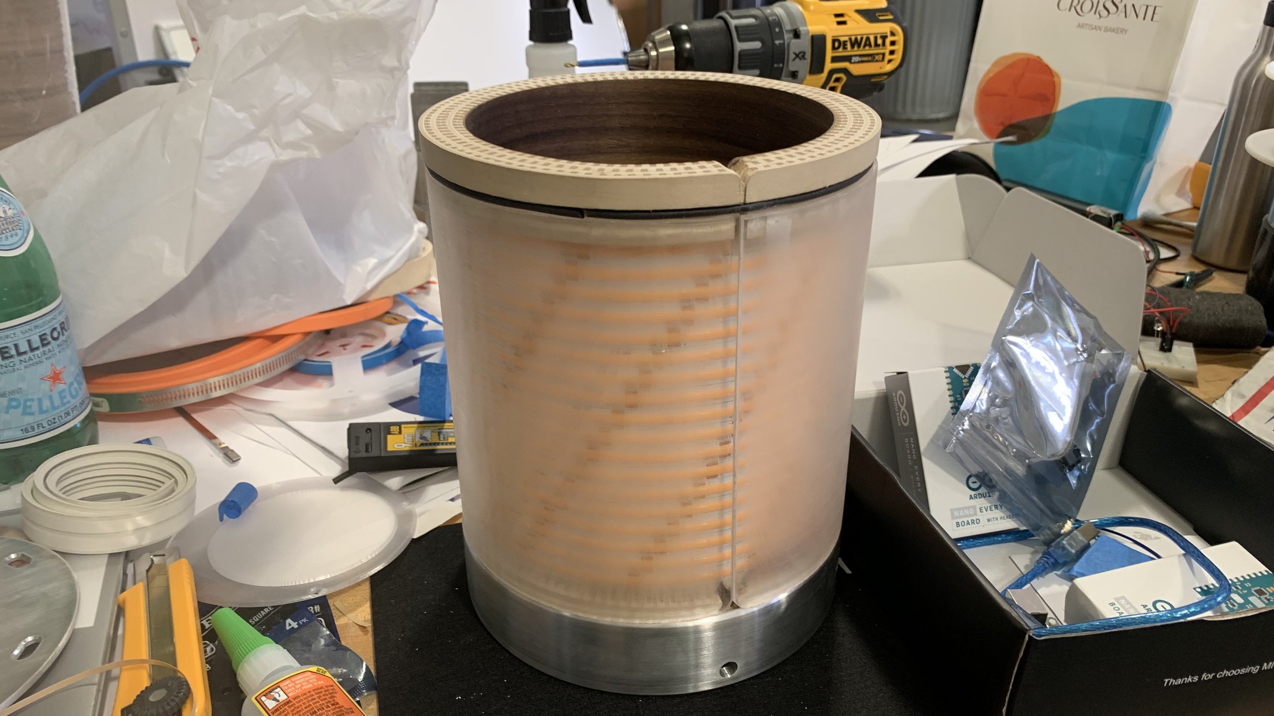
From exterior to interior: a thin sheet of translucent veneer, frosted acrylic, air gap, >32ft of LED strips, and a cylinder of plywood. The top has two extra rings of plywood to prevent the acrylic from showing. The air gap not only allows light to better diffuse, but also allow the wood base to securely slot into. The aluminum base secures the wood base, houses the electronics, and has a barrel jack to supply 24V. An aluminum lid seals the internal and a soft felt pad prevents scratches on the metal and the table surface
A lot of iterations were made. In fact, the final product is v56.

Blueprints
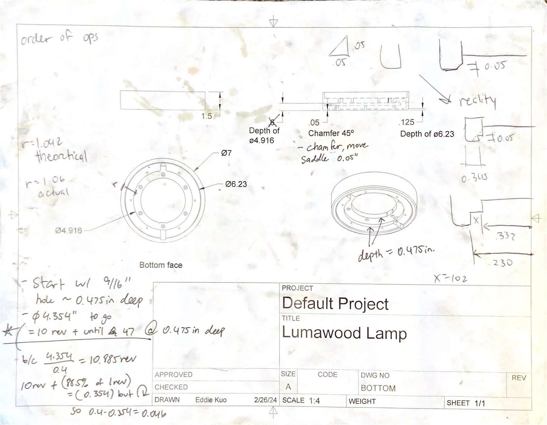
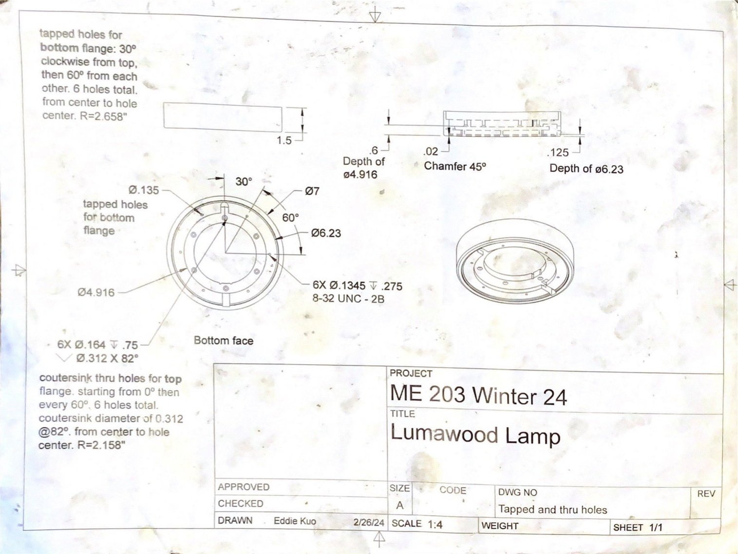
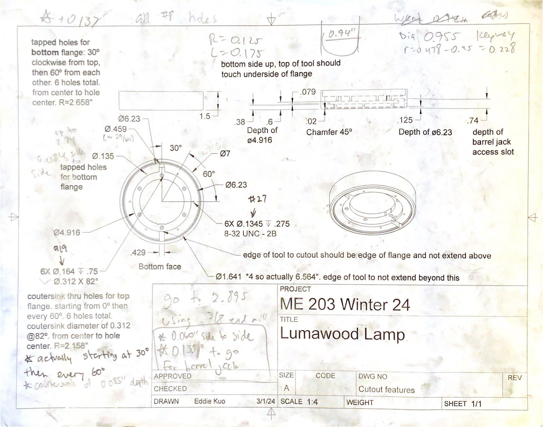
Before machining and building my parts, I created a set of blueprints. Since a lab session is limited to 4 hours, I made sure to not bite off more than I could chew. Even when blueprints were partitioned according to time limits, mistakes can come up causing delays and many have.
Coming into the lab with knowledge of the order of operations prepared saves a lot of time as I have come to learn.
I would have reminders, calculations, order of operations, and ideas to fix my mistakes jotted down all around the original blueprints.


Woodworking experimentation
My project was considered a red flag as it included experimental features in addition to the required machining processes. I had to immediately start exploring them.
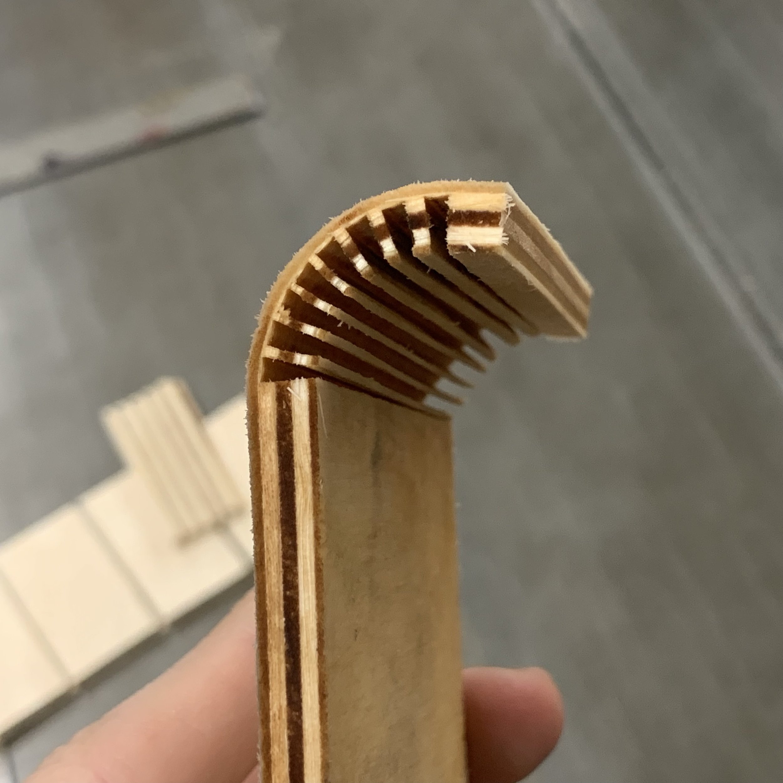
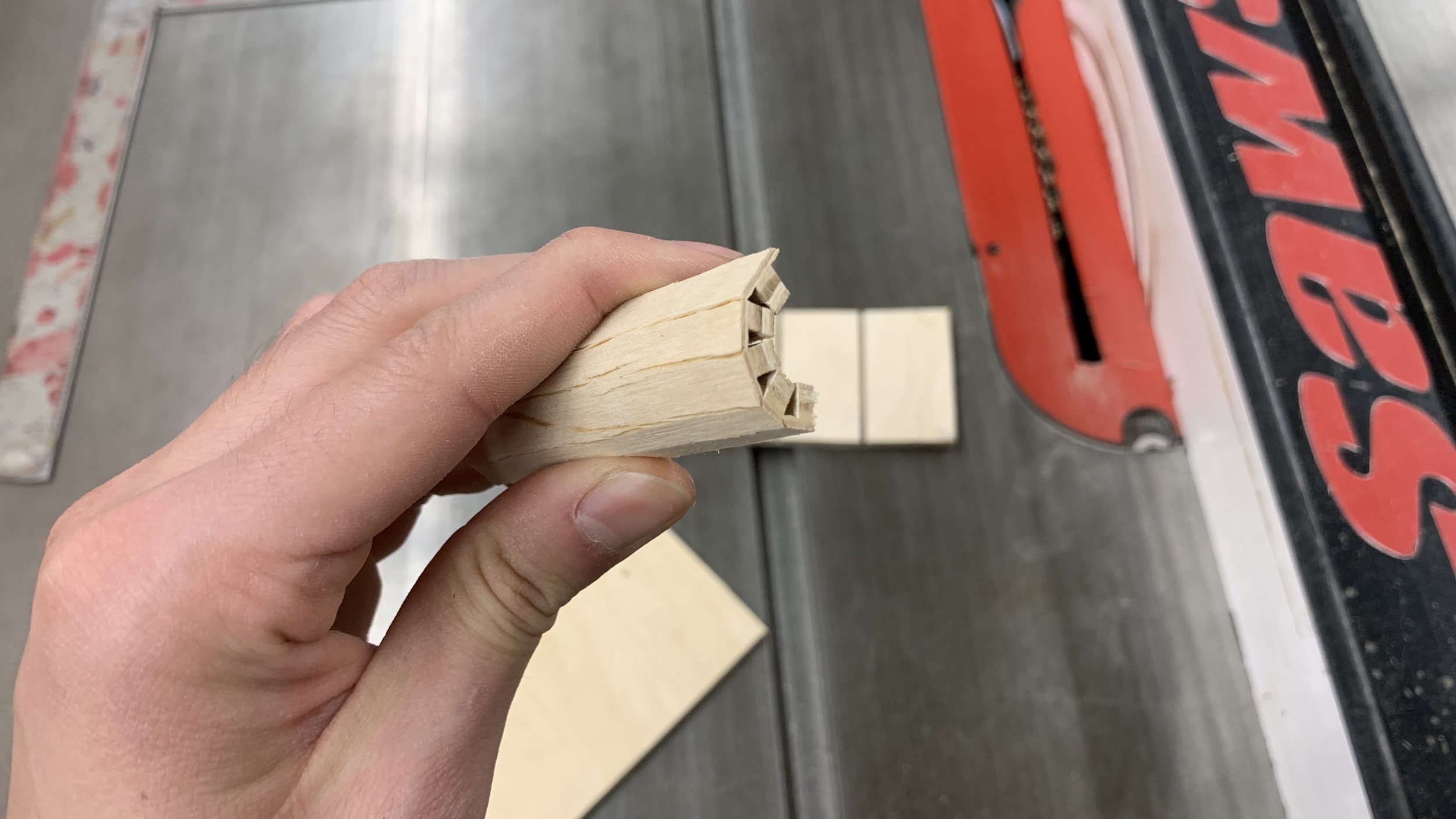
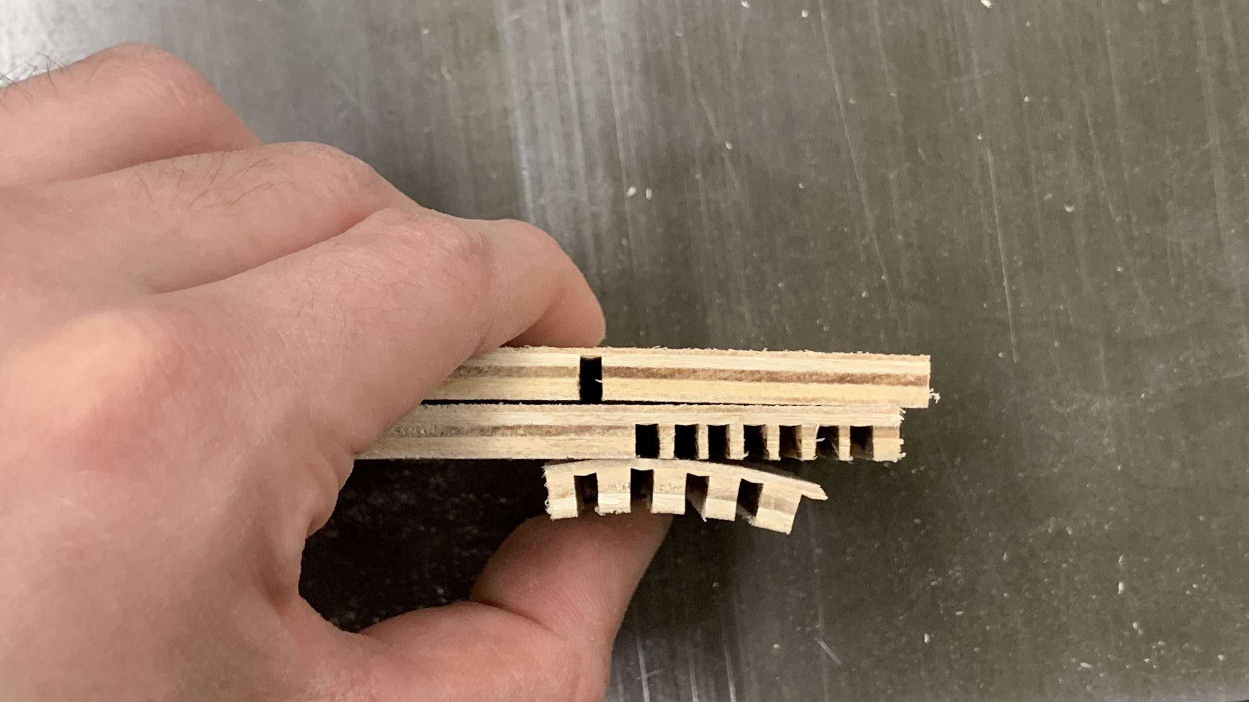
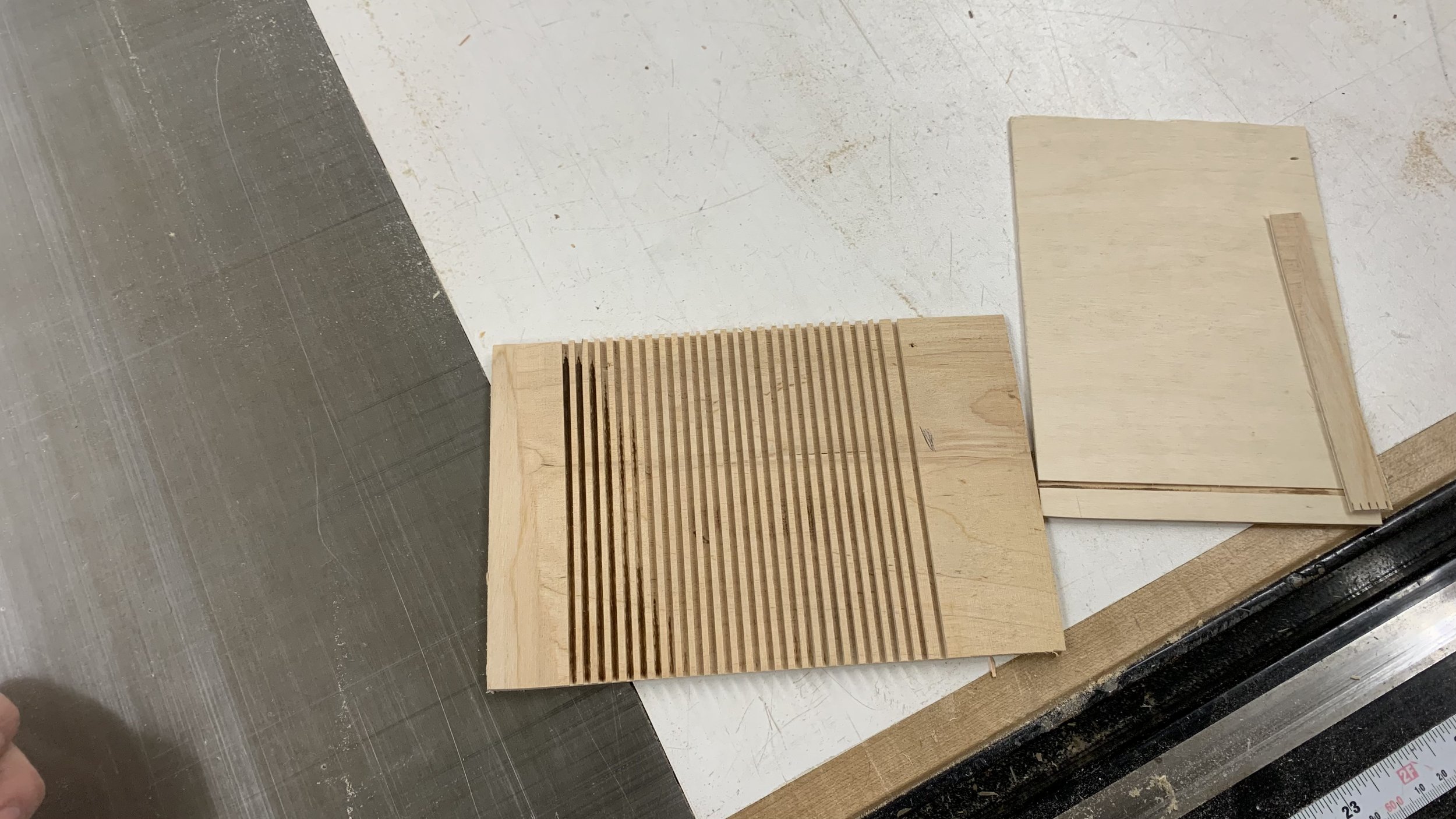
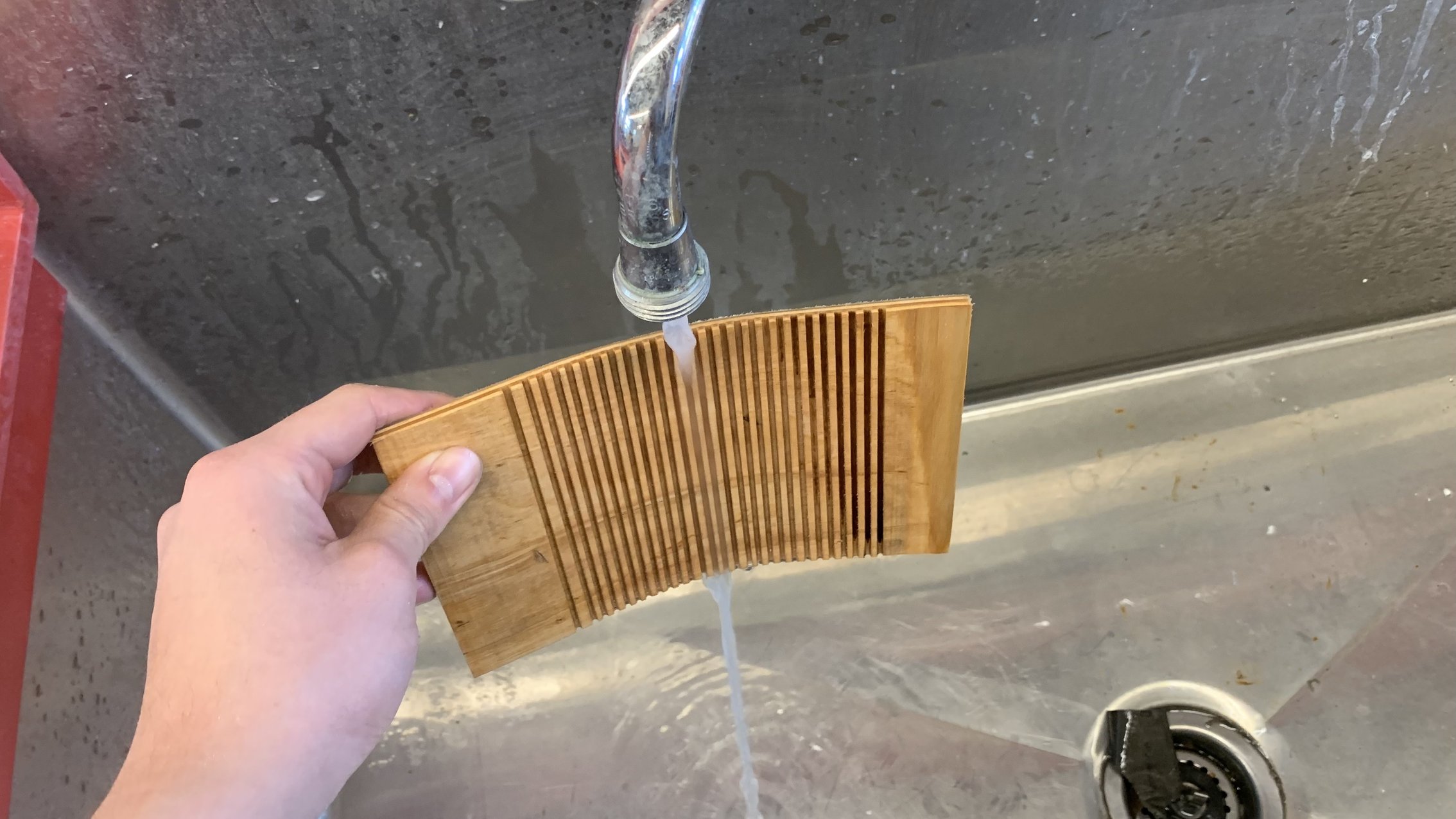
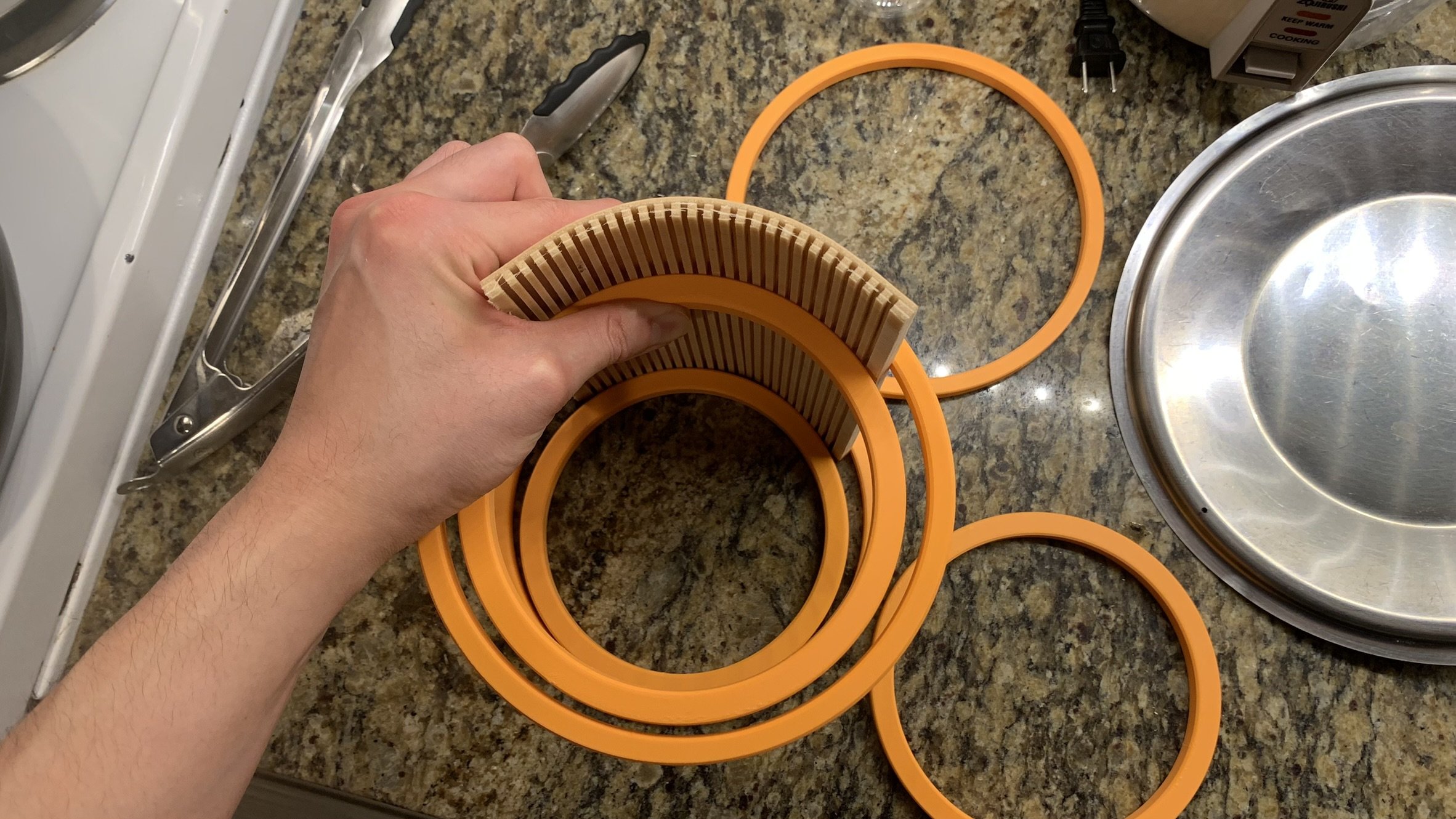
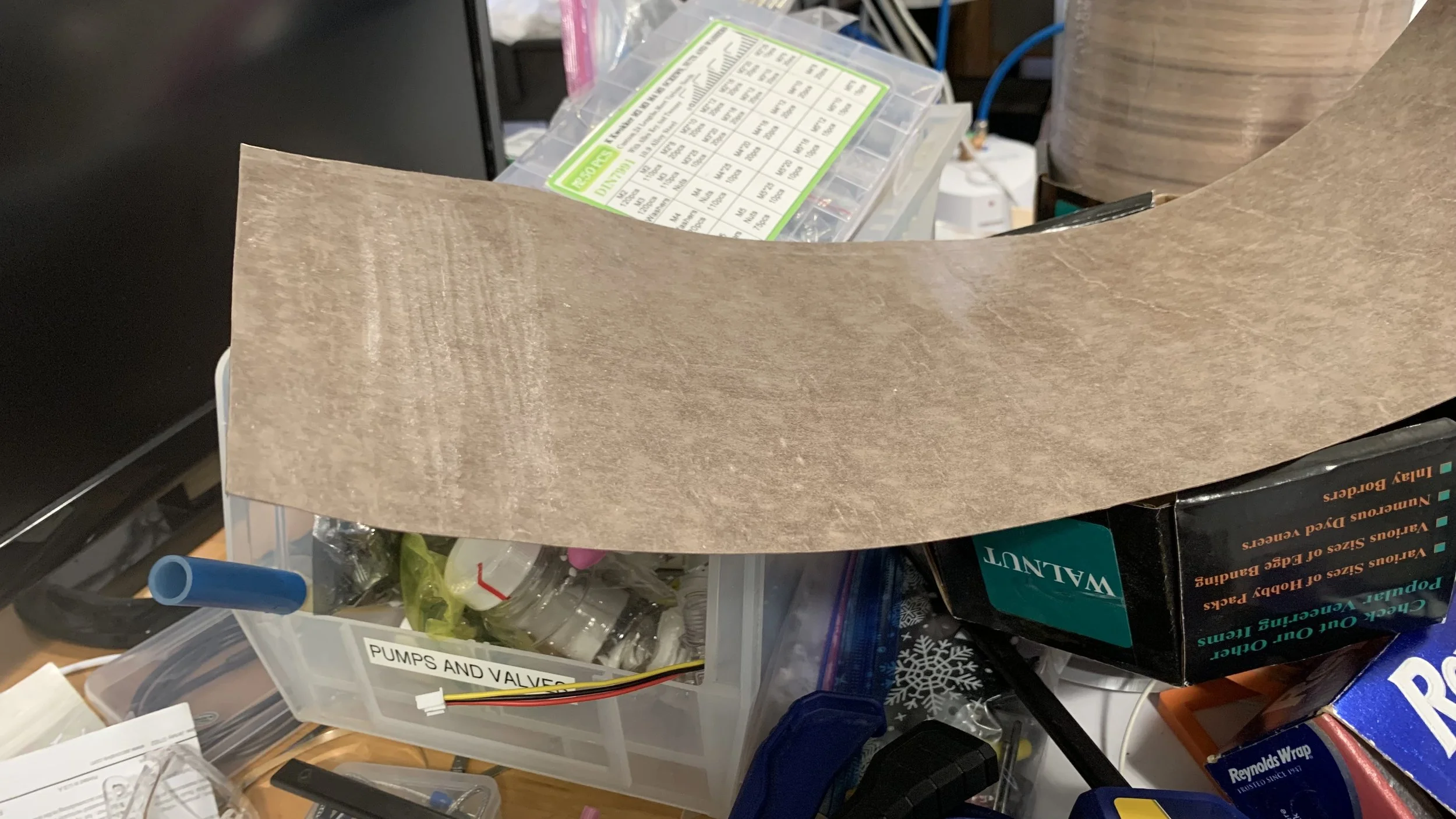
First up was kerf bending. Given the blade width, I had to find the optimal kerf and blade depth such that the 1/4” plywood would bend without splitting. Too low of a resolution will show flat edges, too high will affect the structural integrity. Soaking it in water helped increase the pliability.
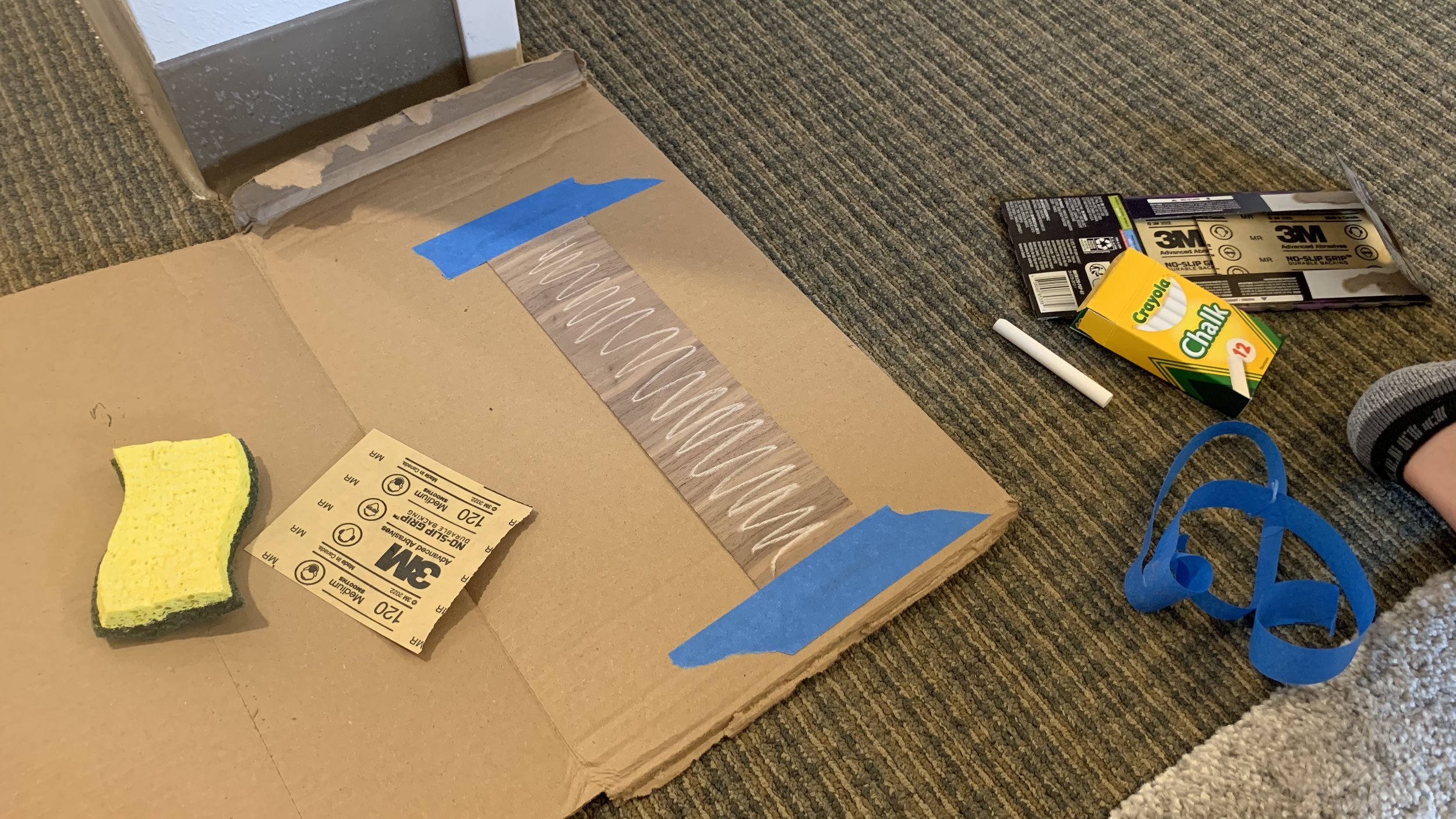
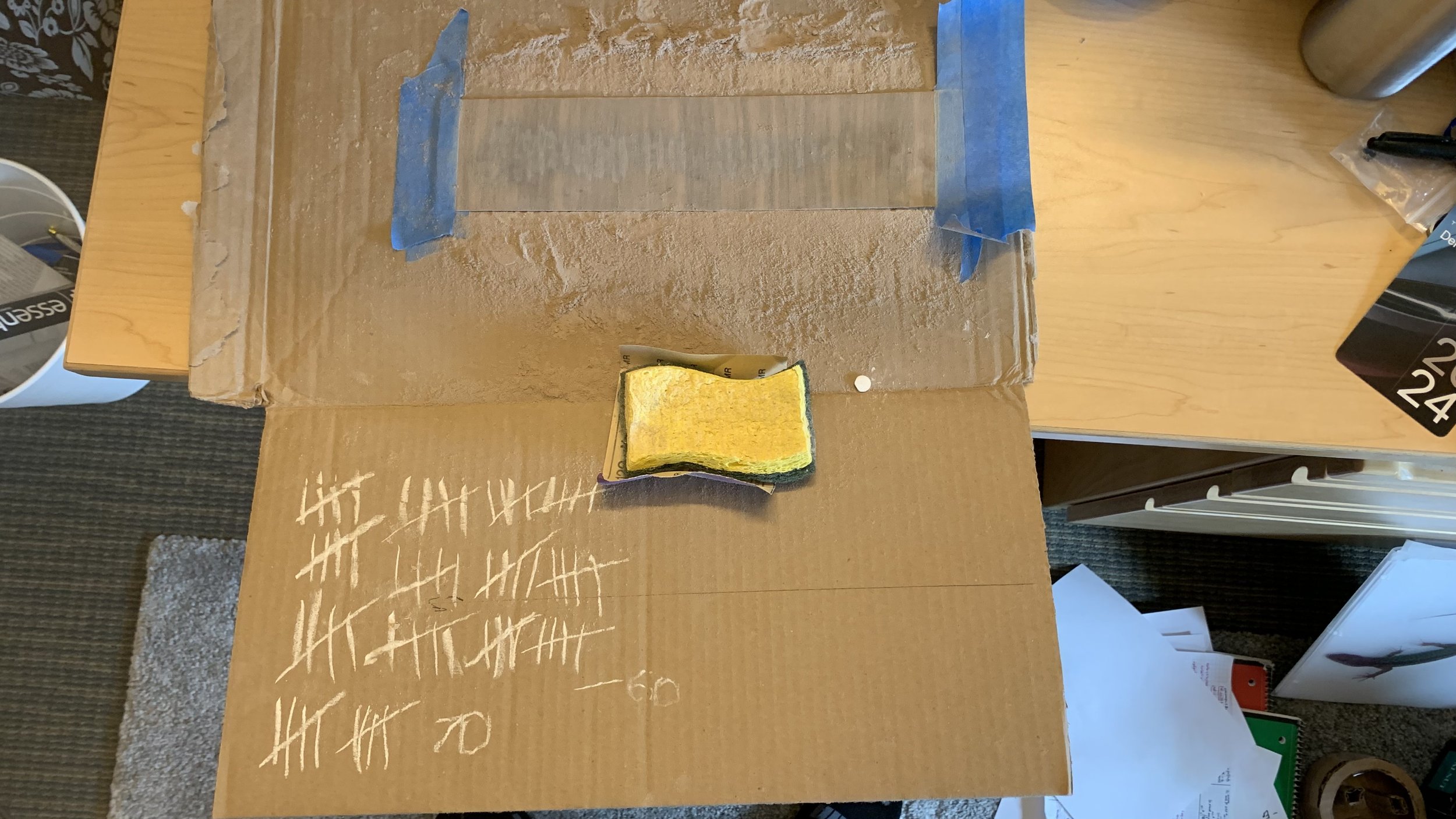
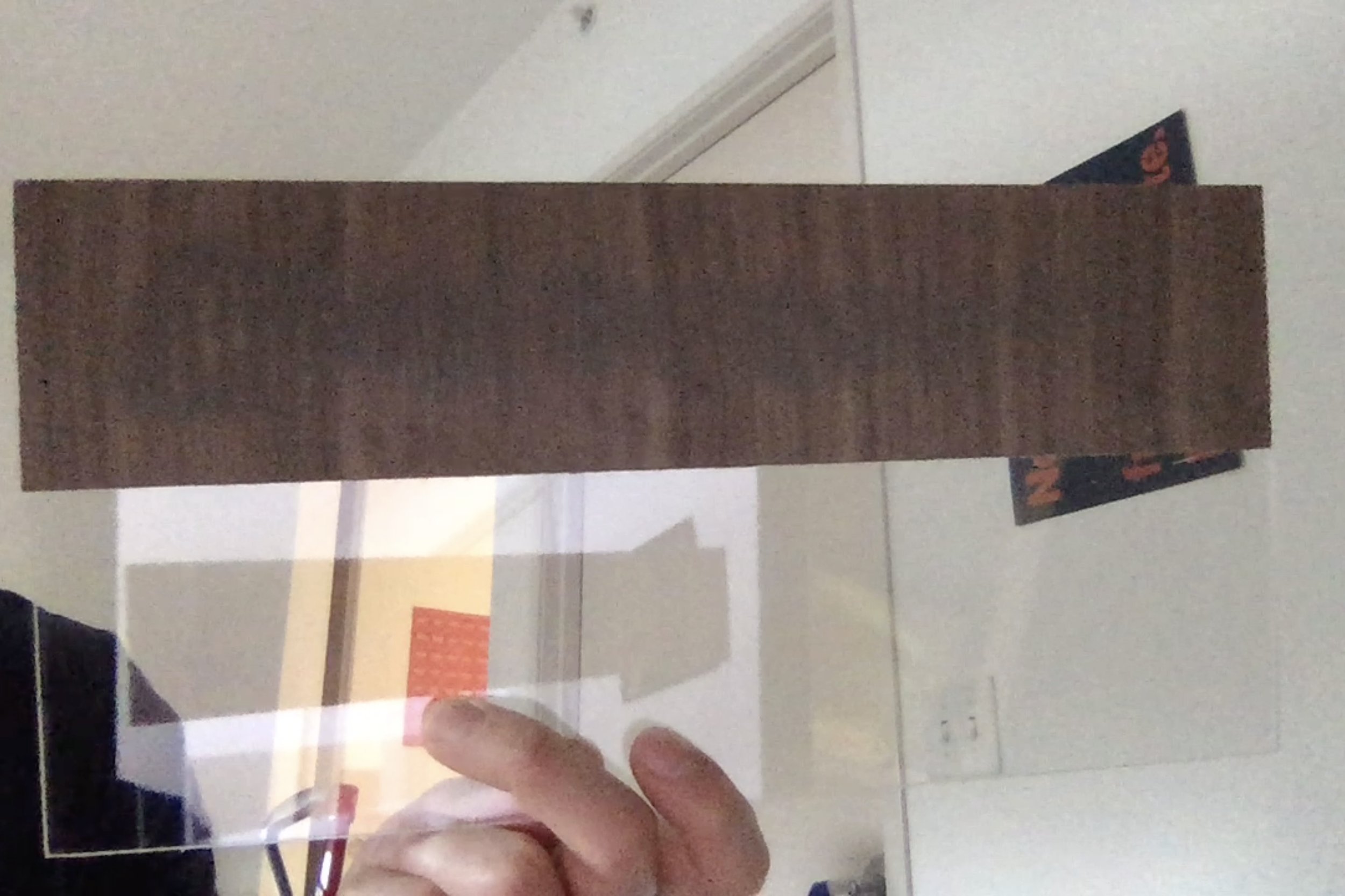
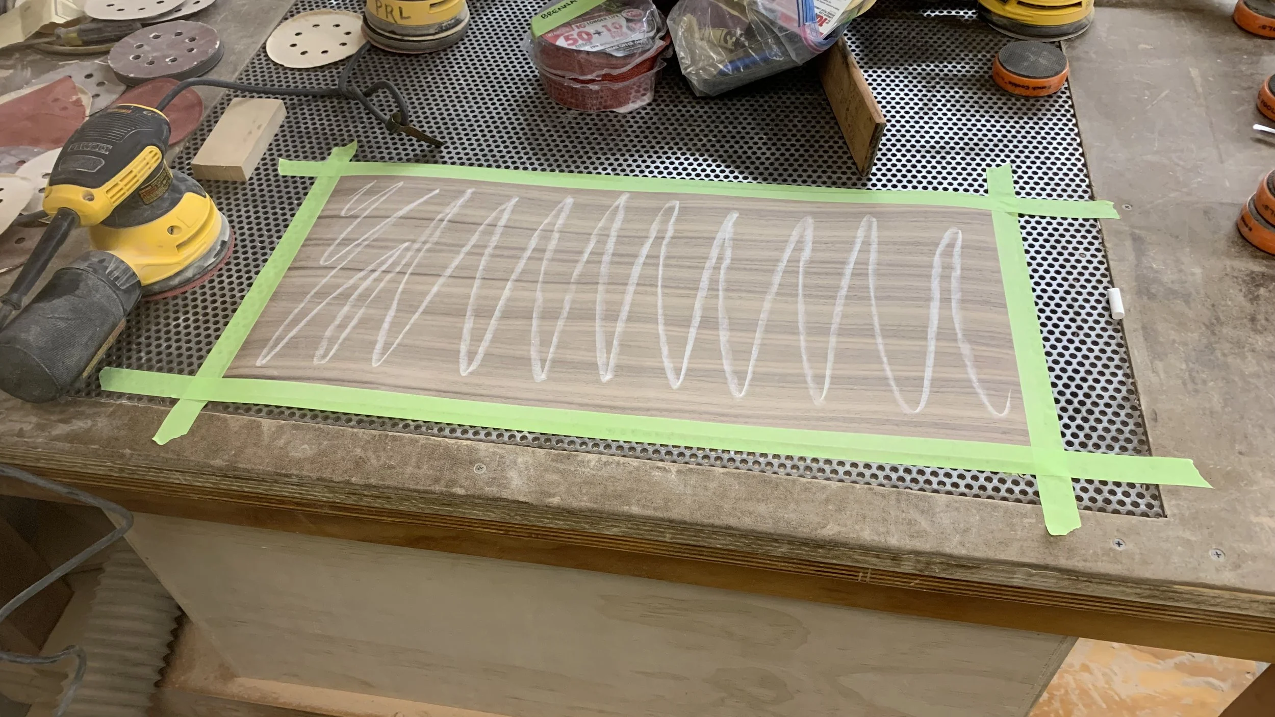
For the veneer, I started with 2/59” thick test strips. Using chalk allows me to visually see where I’ve sanded. After 120-140 passes with 220 grit sandpaper, light shone through at the cost of a broken grain structure. This was not going to be easy.
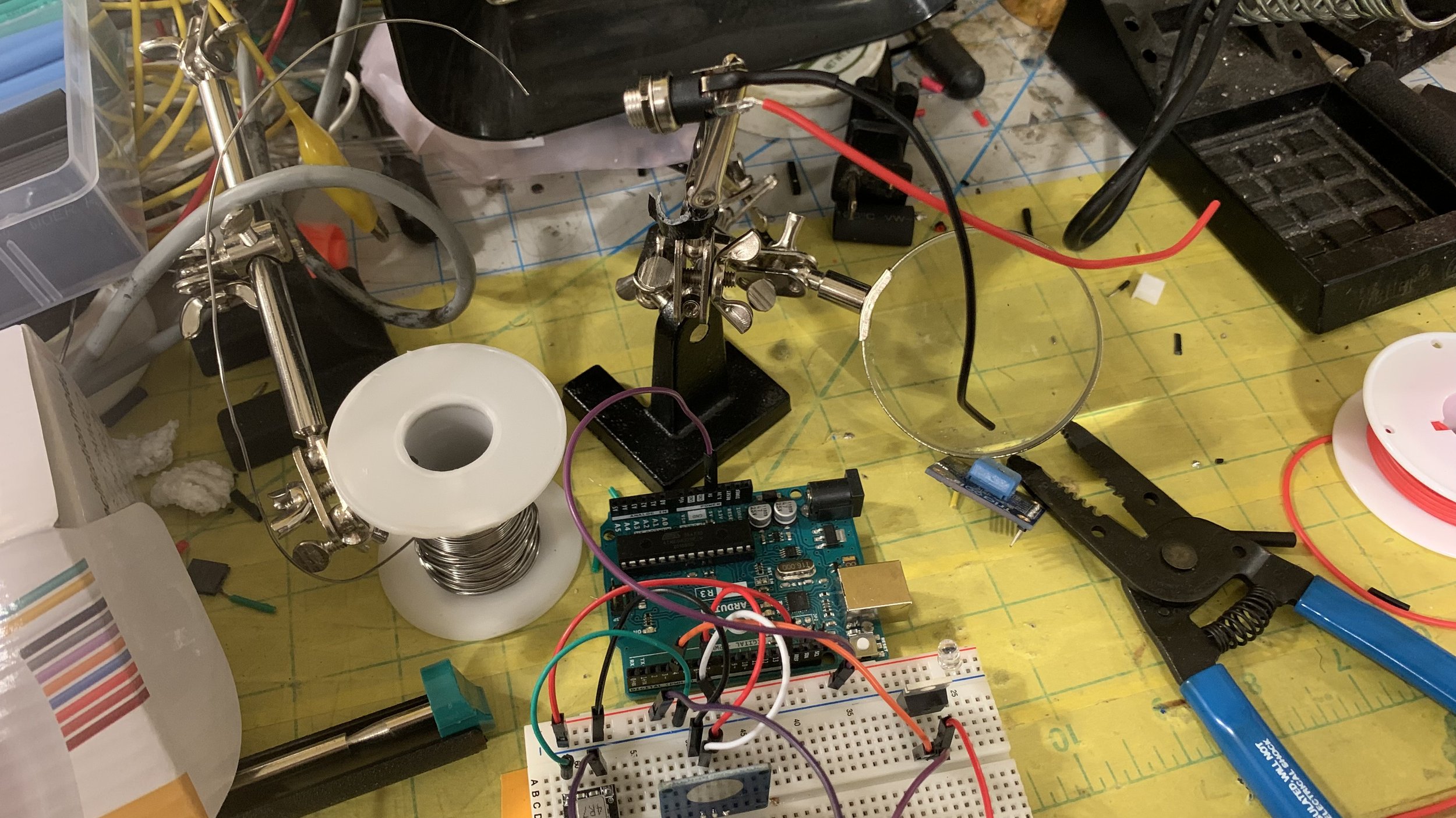
Electronic magic
I avoid electronics like a plague. I’m not good at it and coding puts me to sleep. Literally. To conquer my fear, I had to incorporate some form of it into my project.
I let my ego go and was never too proud to ask for help. Since I believe it was going to be one of my biggest hurdles, I immediately went to work on it.
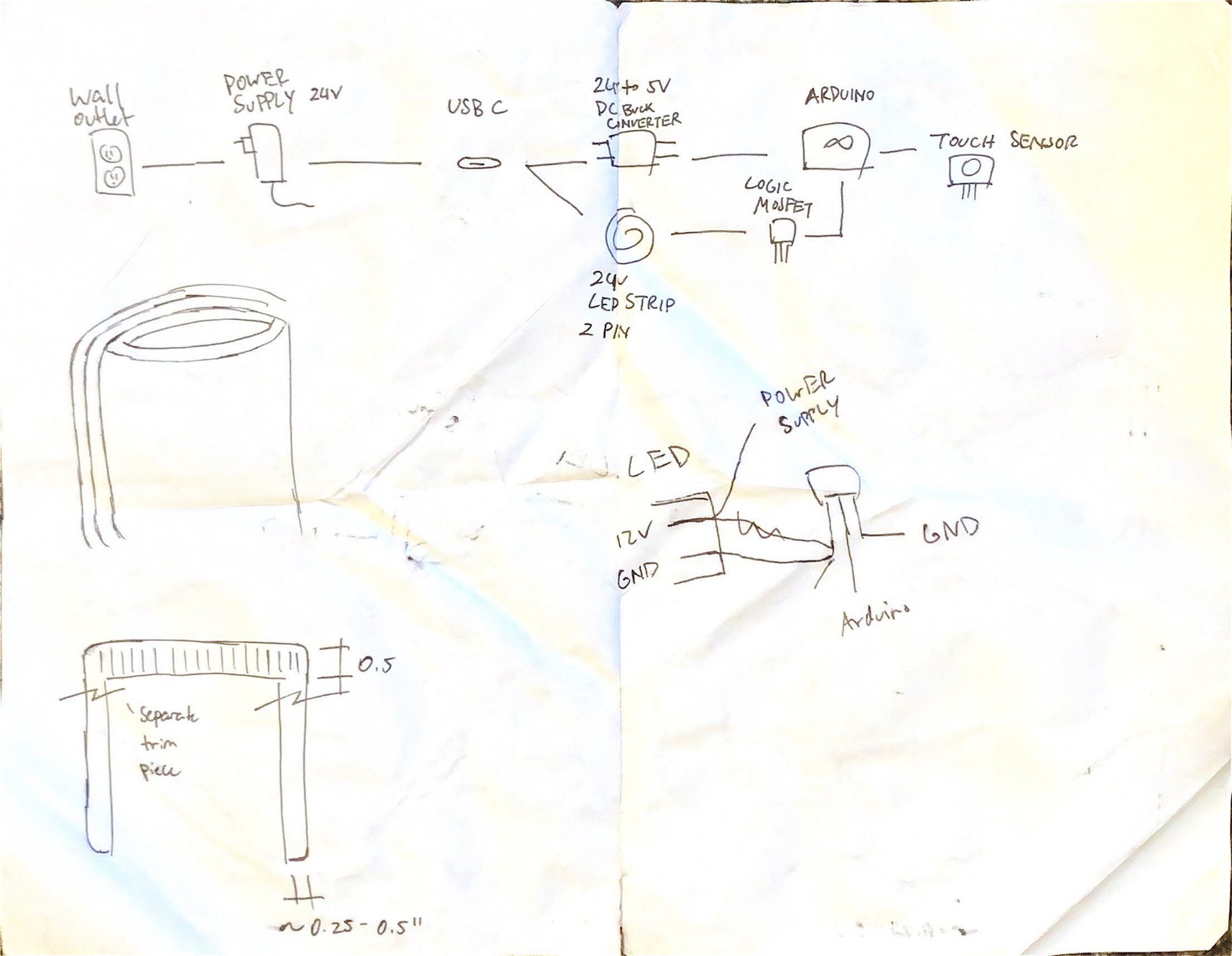
The entire aluminum band will act as as a button for the lamp. You tap it to turn on/off. Tapping and holding will not trigger uncontrollable flashes. It simply works like magic.
Soul of the lamp
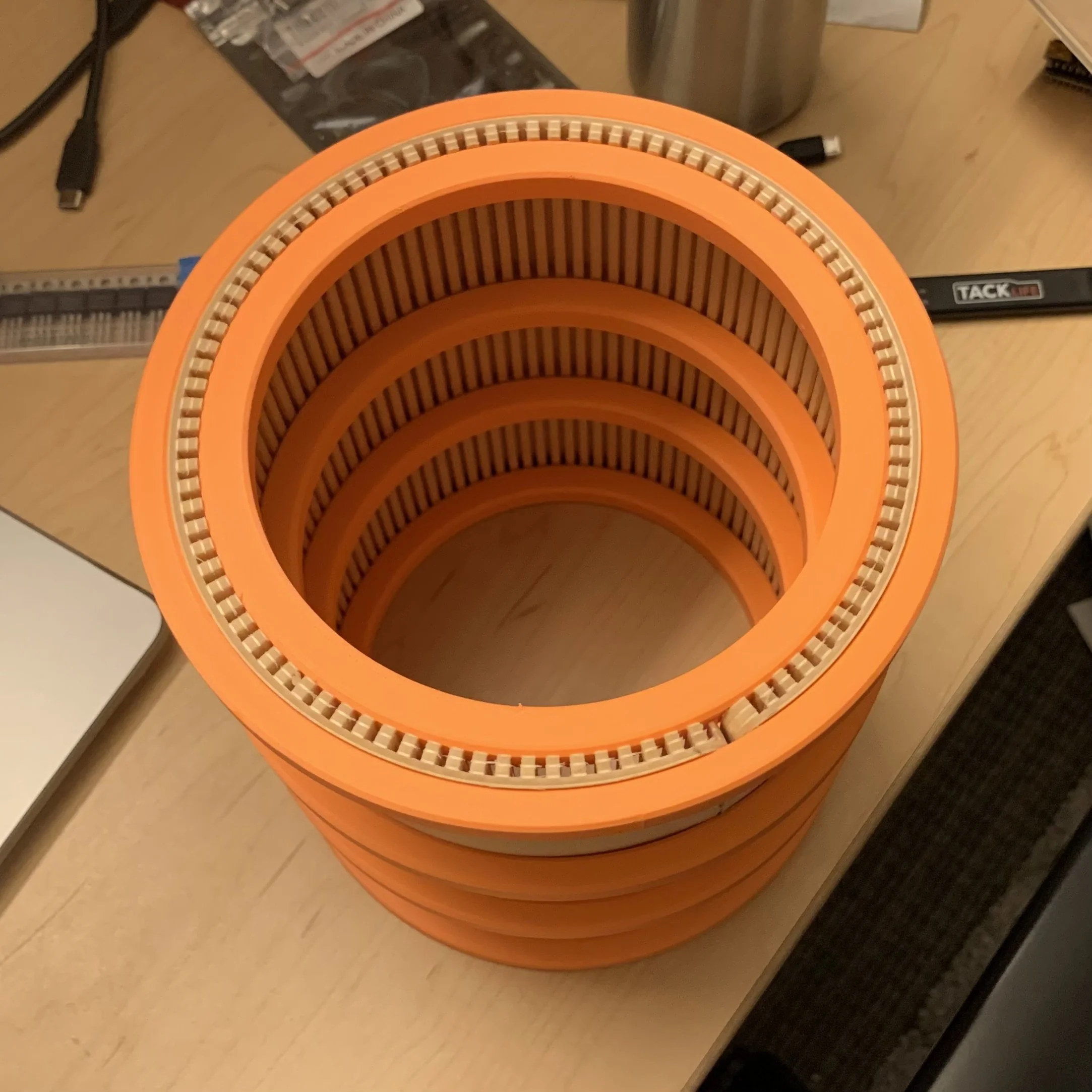
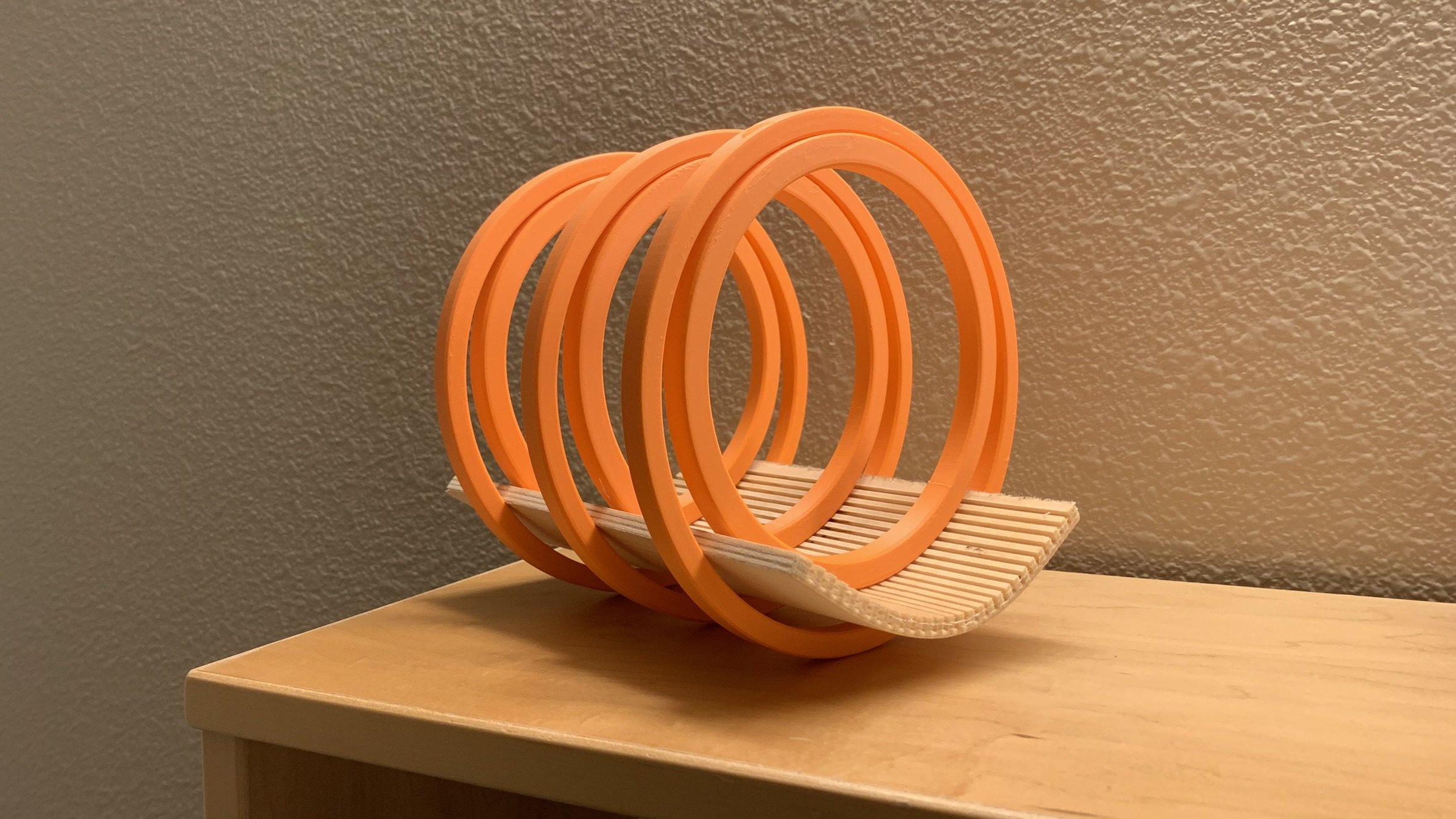
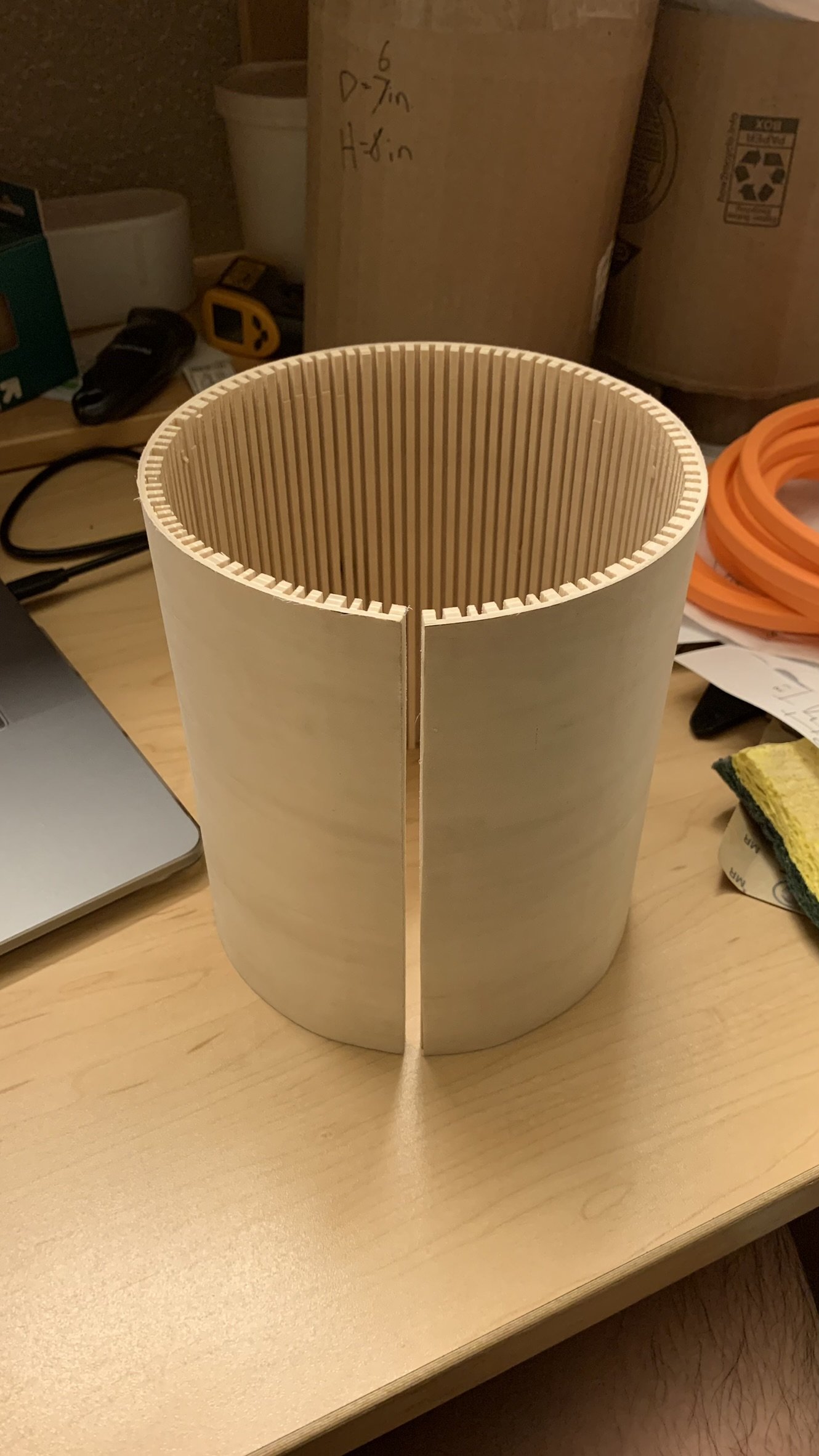
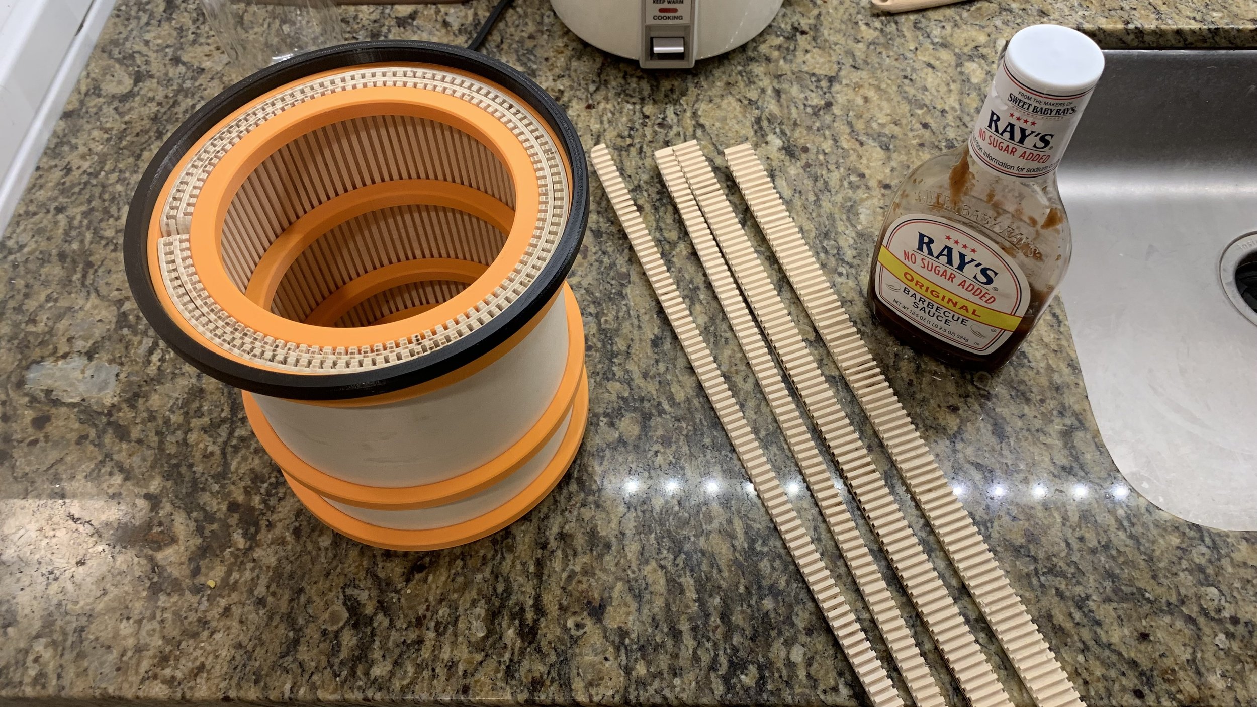
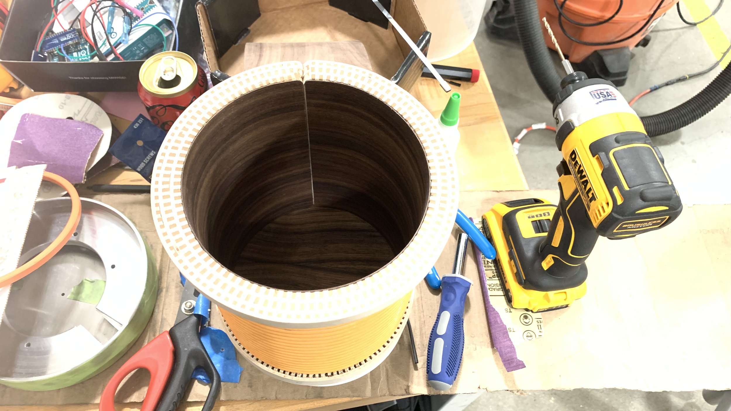
Now that I’ve got the hang of kerf bending. It was time to finalize a critical part: the soul of the lamp. With each kerf at a 5mm spacing and the fact that the first piece had a glue meltdown scenario, I made well over 200 passes on the saw stop just for the body.
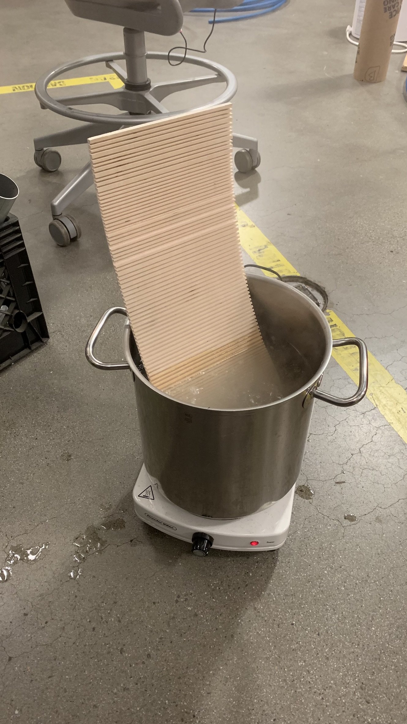
Using a hot water soak, I successfully bent another test piece (this was from the same plywood as my final as pliability differs across plywoods). This method however failed when it came to the full cylindrical piece. The water weakened the adhesive between the layers caused it to start chipping as the retention rings were press fitted (the rings allows the piece to hold its shape as it dries over 24 hours.
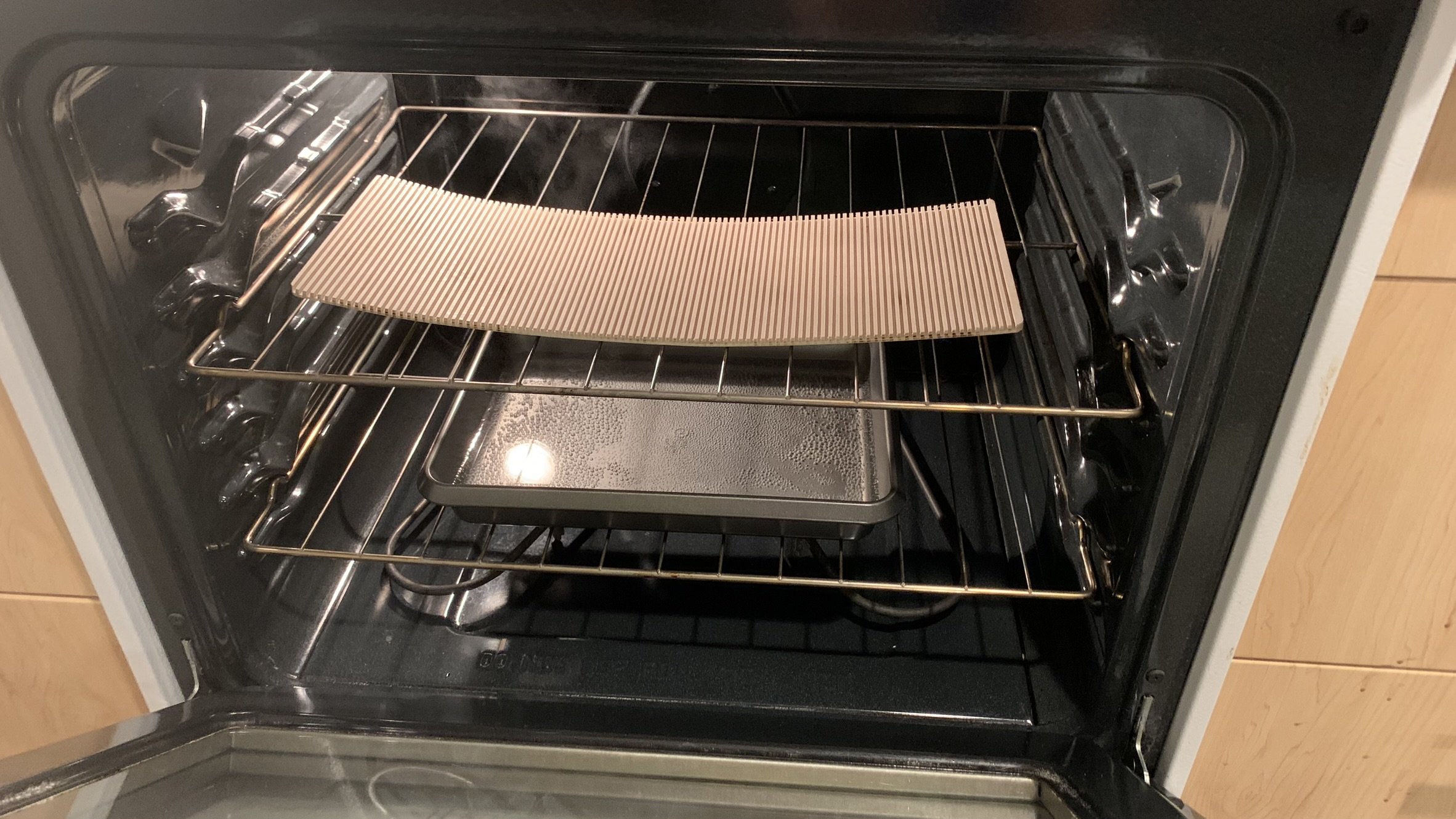
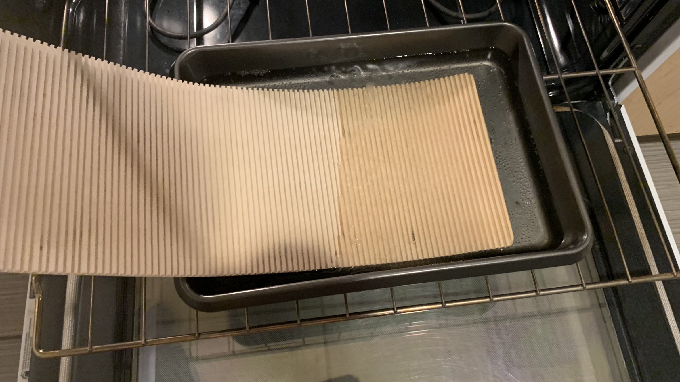
Through trial and error, I decided to bake it in the oven at 215ºF with a bain-marie for 15 minutes. Then, it goes through a quick soak in the bain-marie before bending.
Never would I thought cooking would be involved in making a lamp.

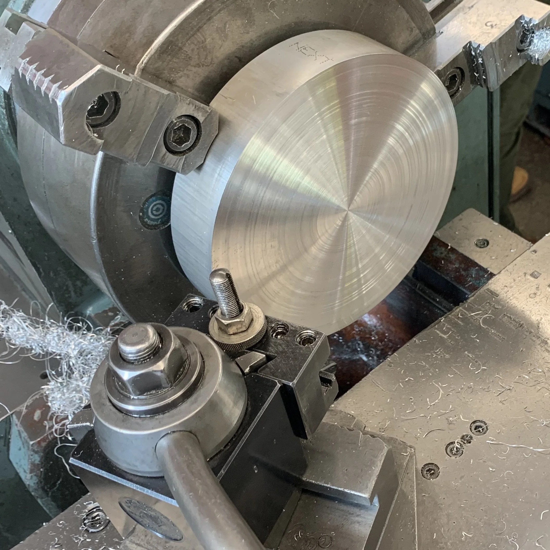
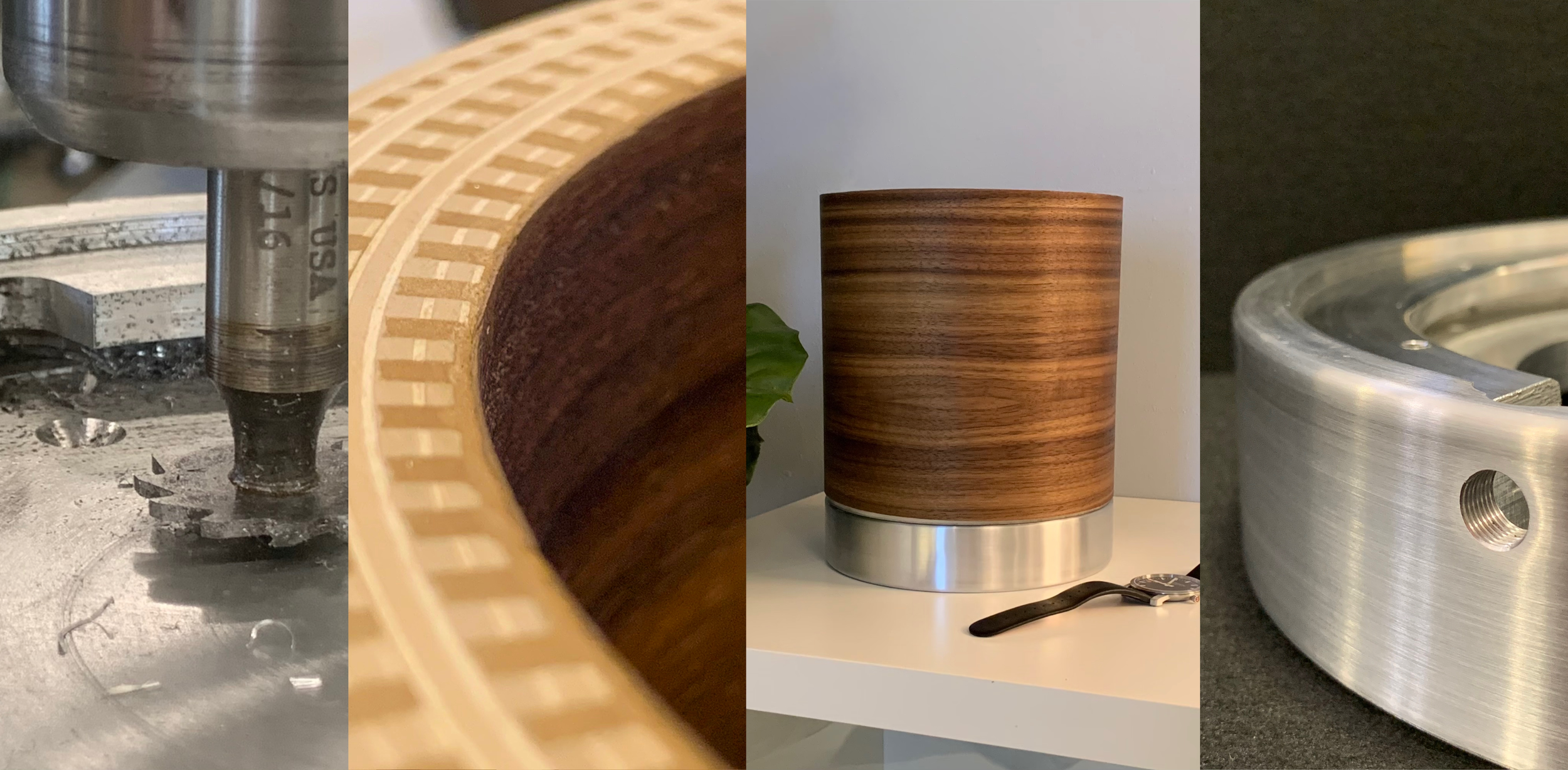
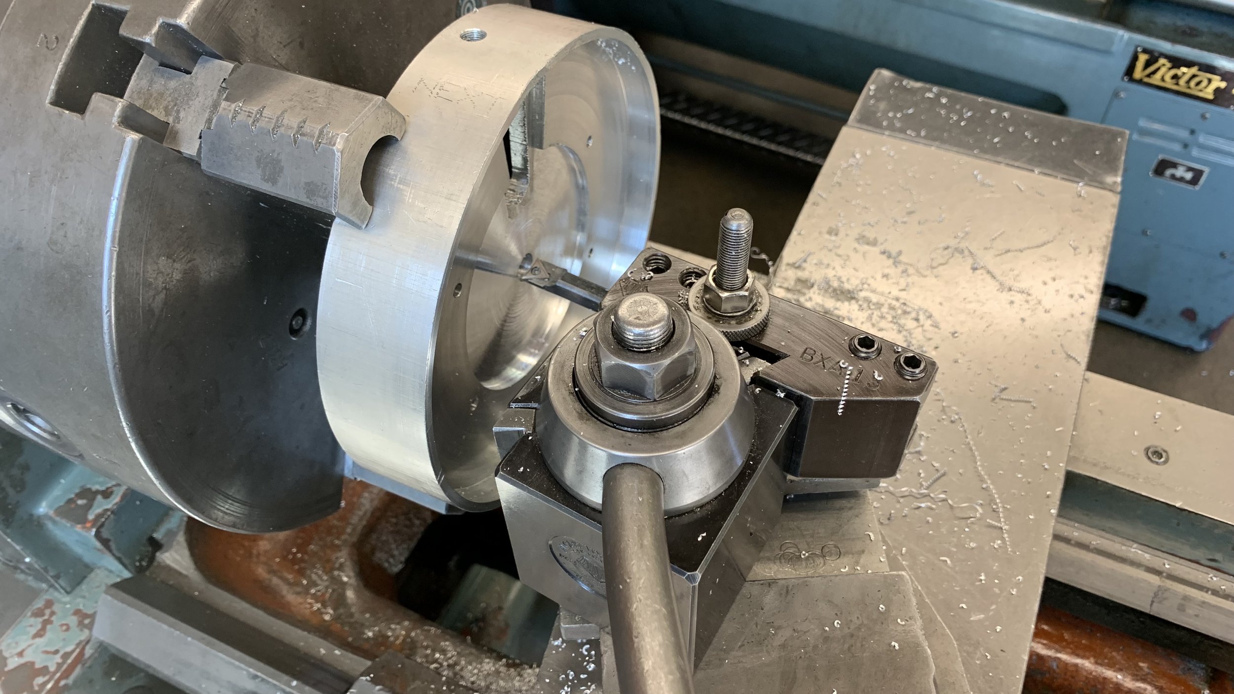
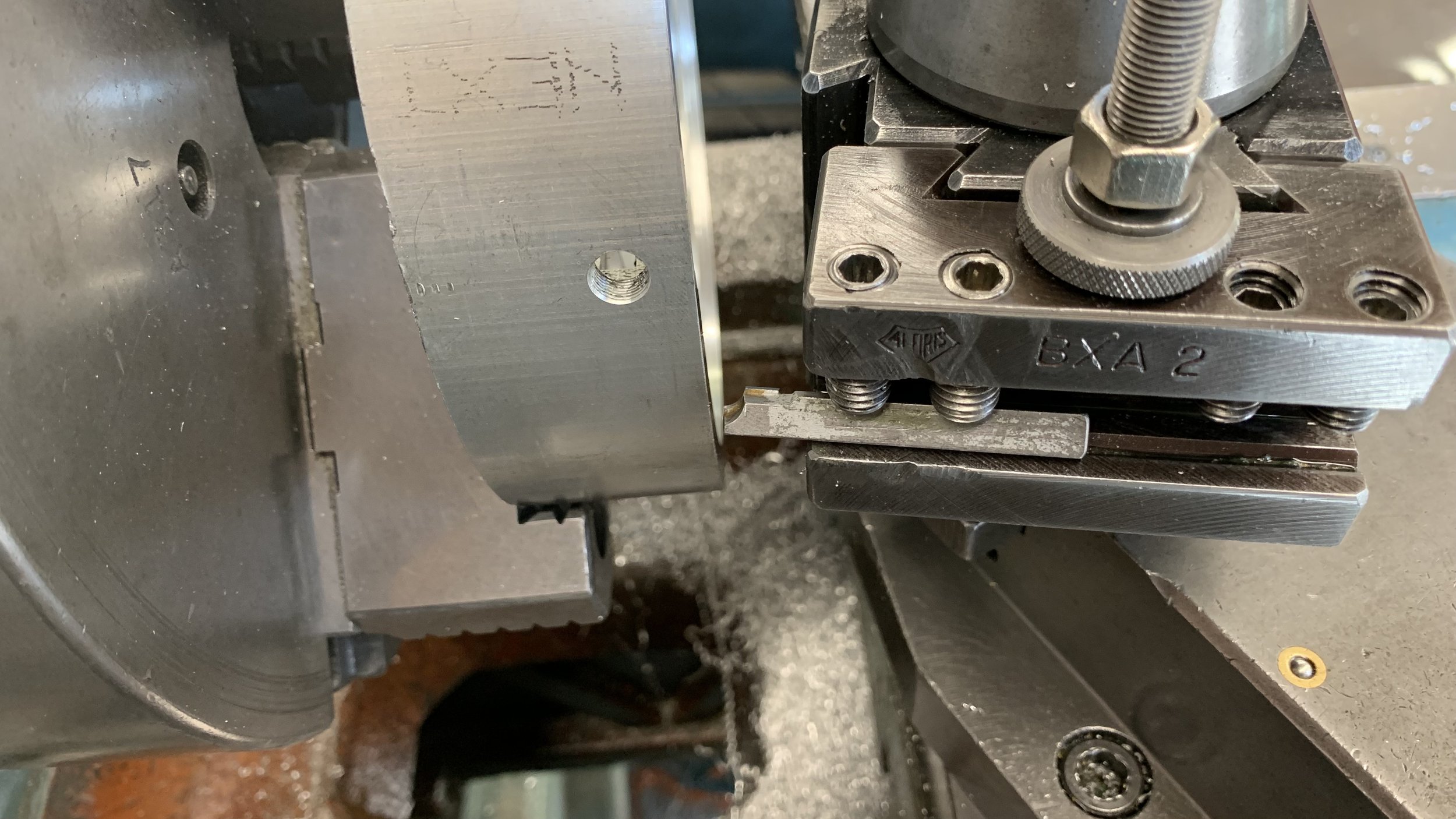
Machining
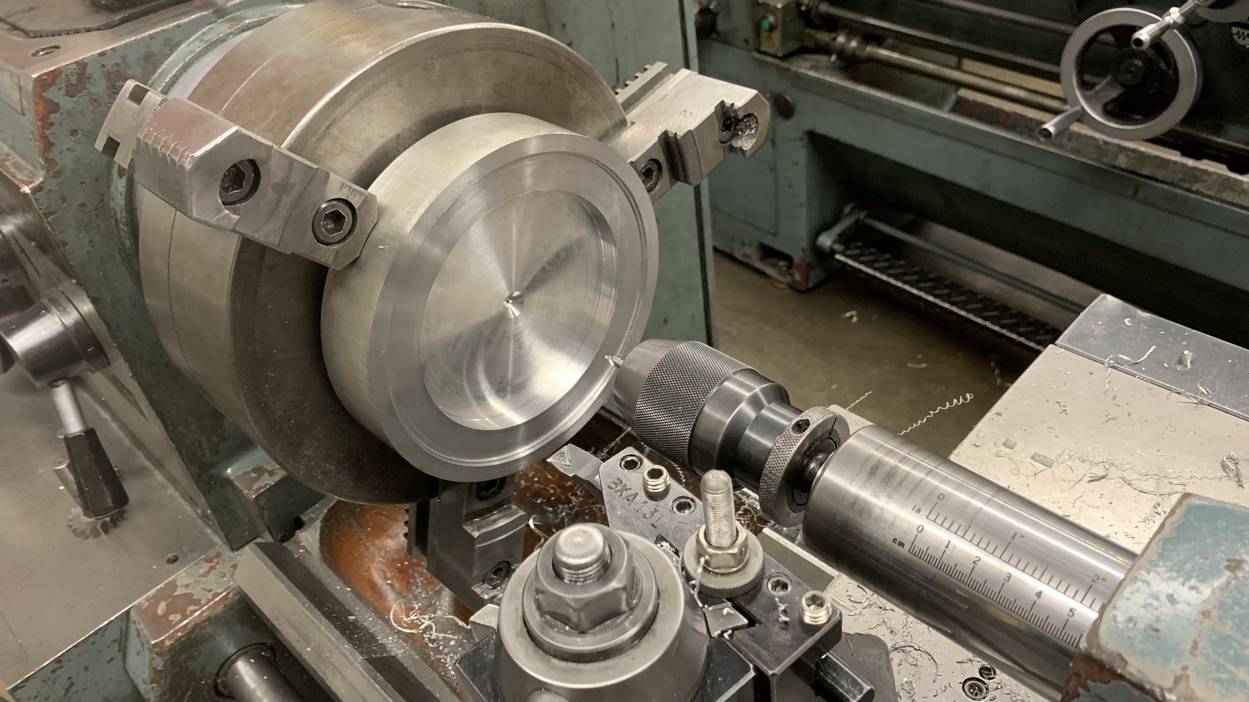
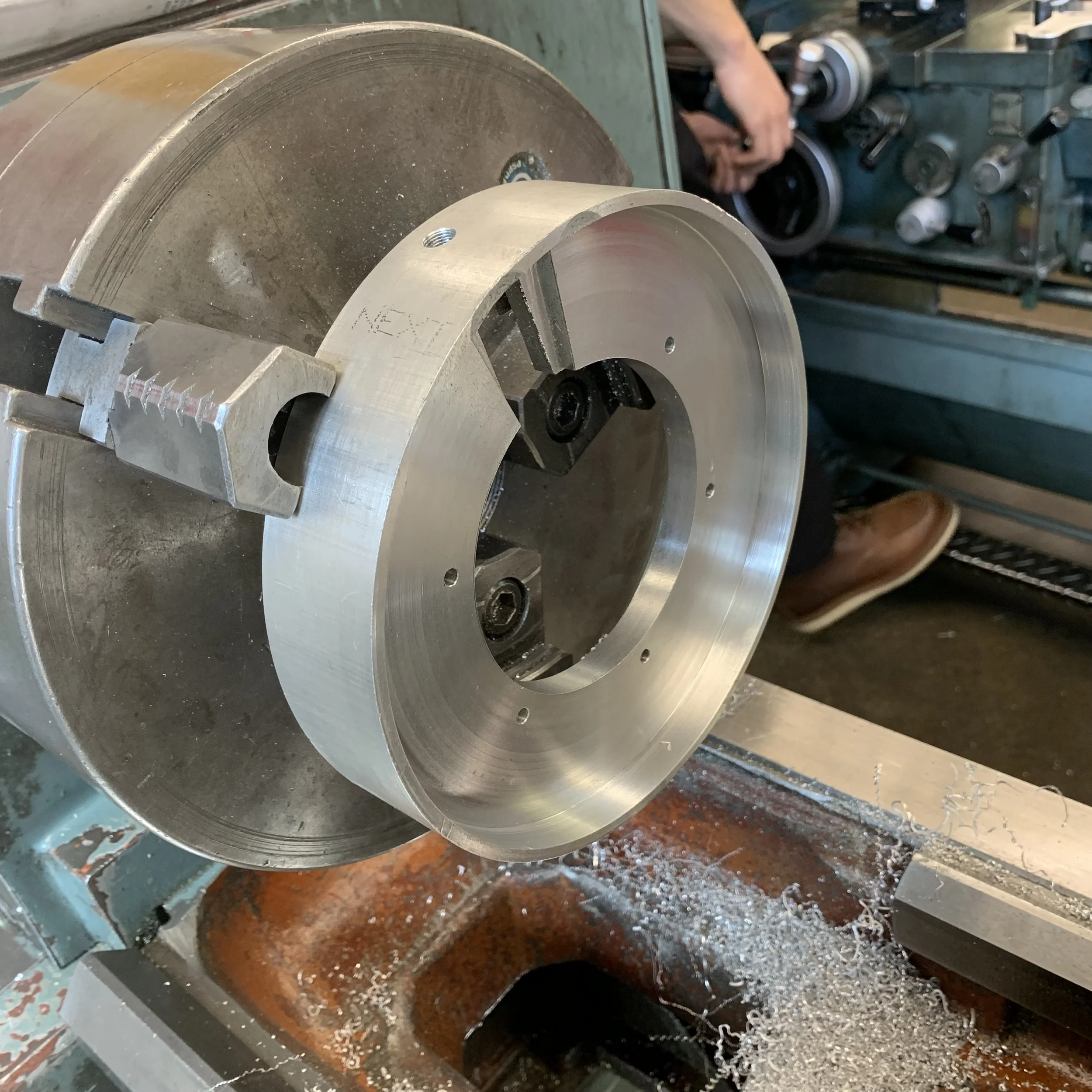
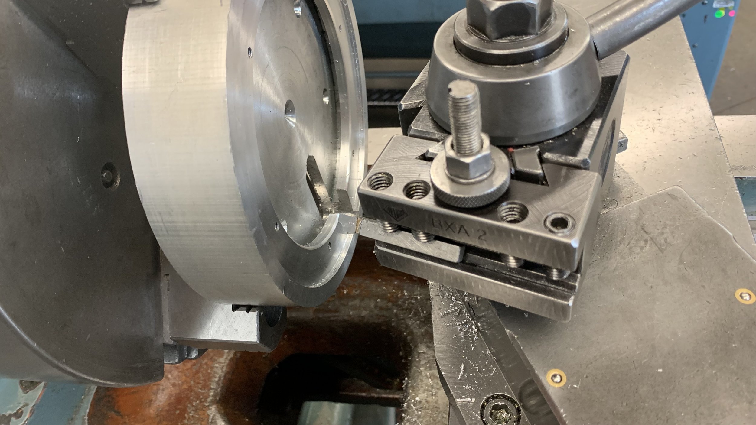
It wasn’t until the workpiece flung off the machine in a much later session did I realize how dangerous my round bar was. Even with inverted jaws on the lathe’s biggest chuck, it was secured only with the last thread.
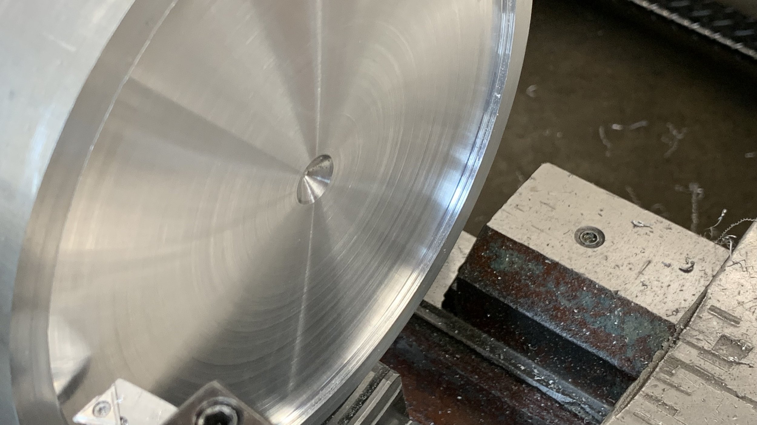
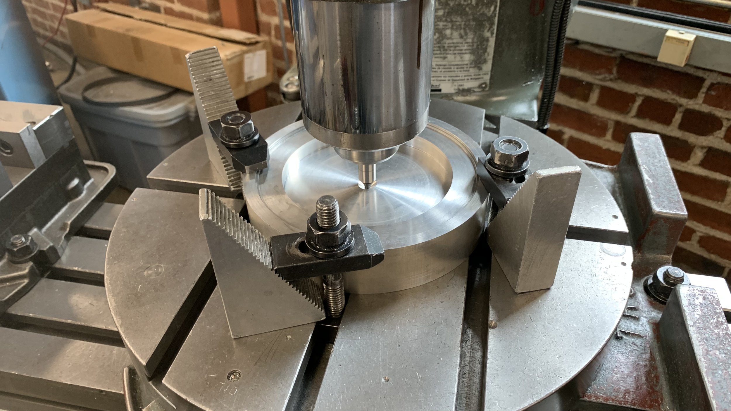
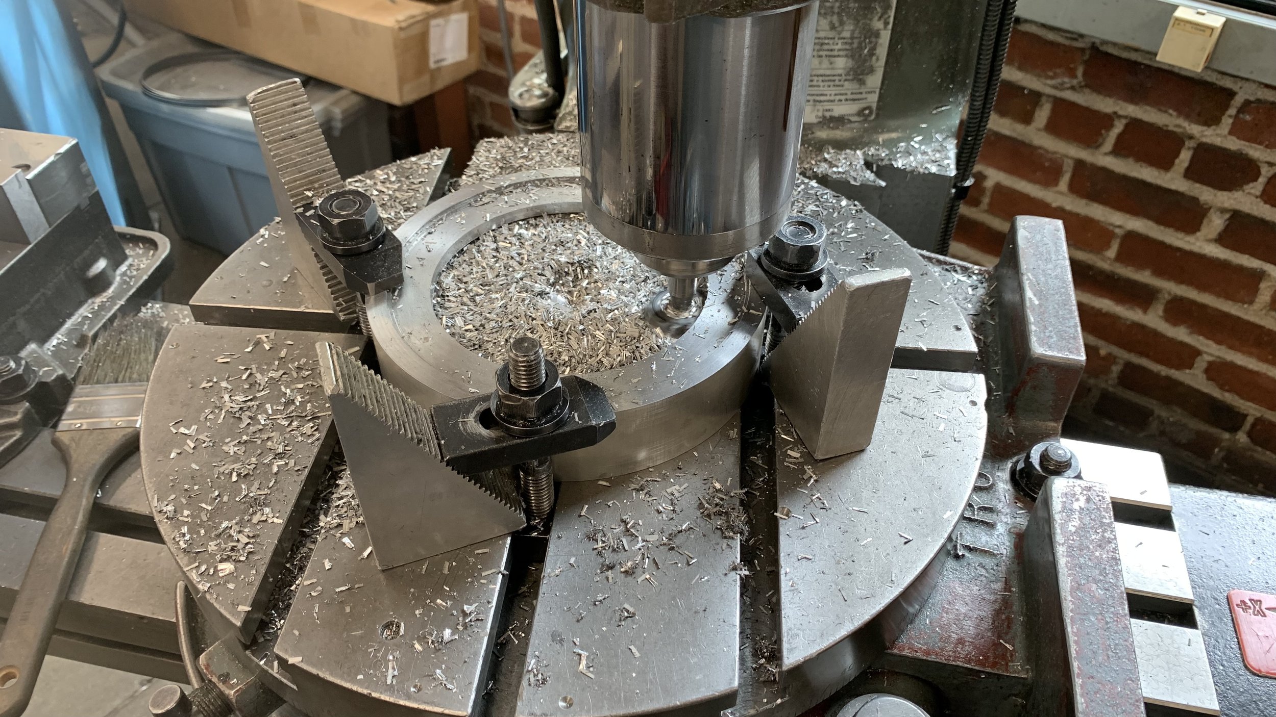
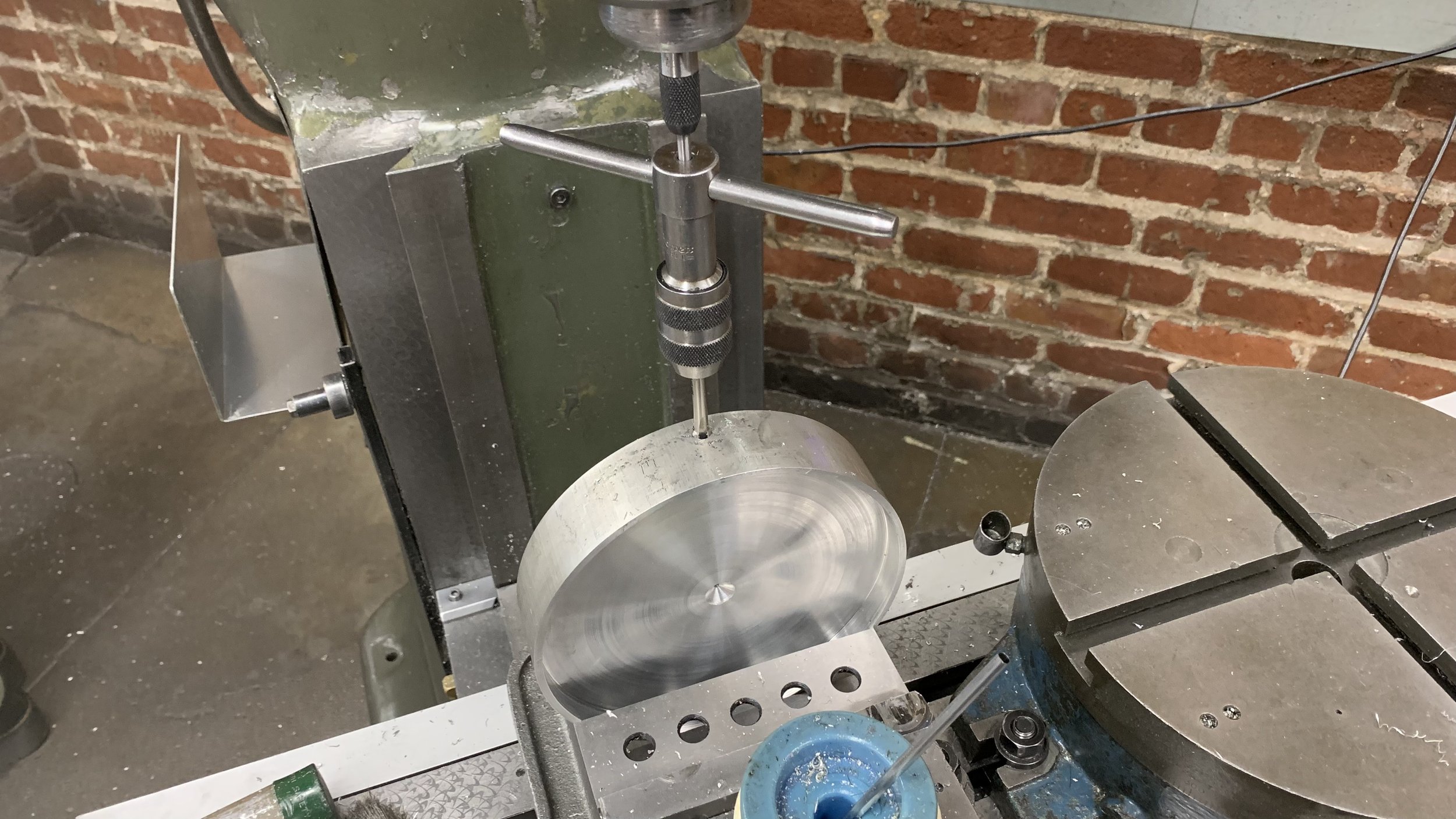
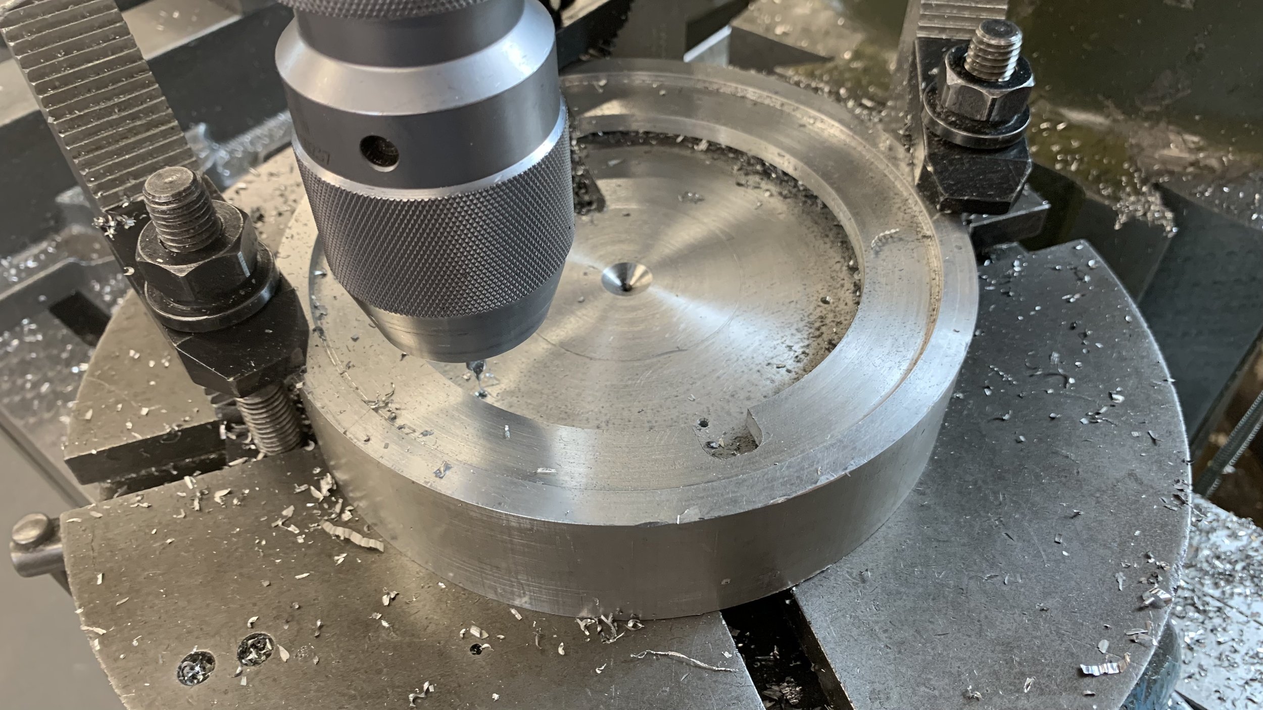
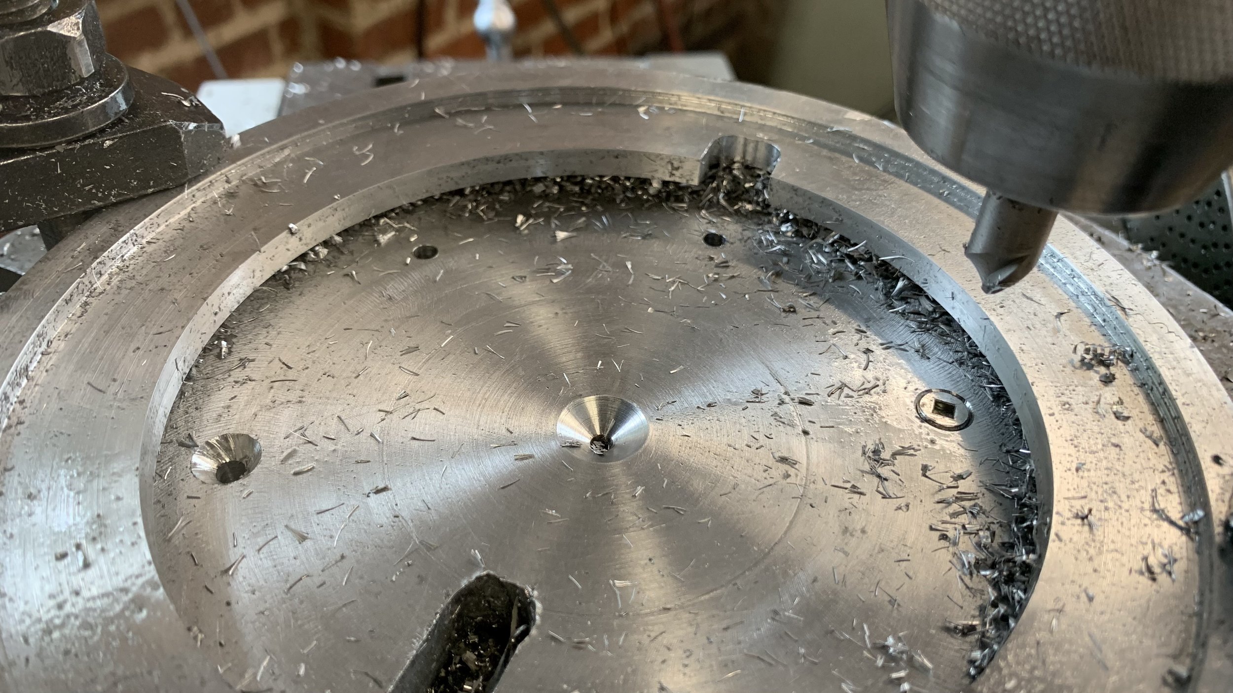
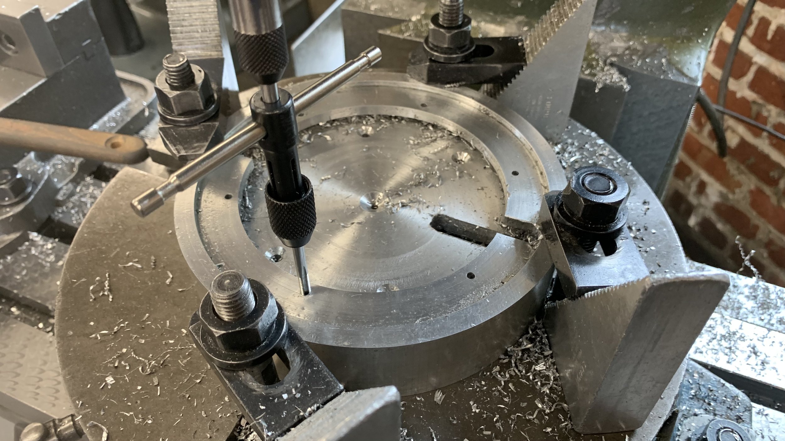
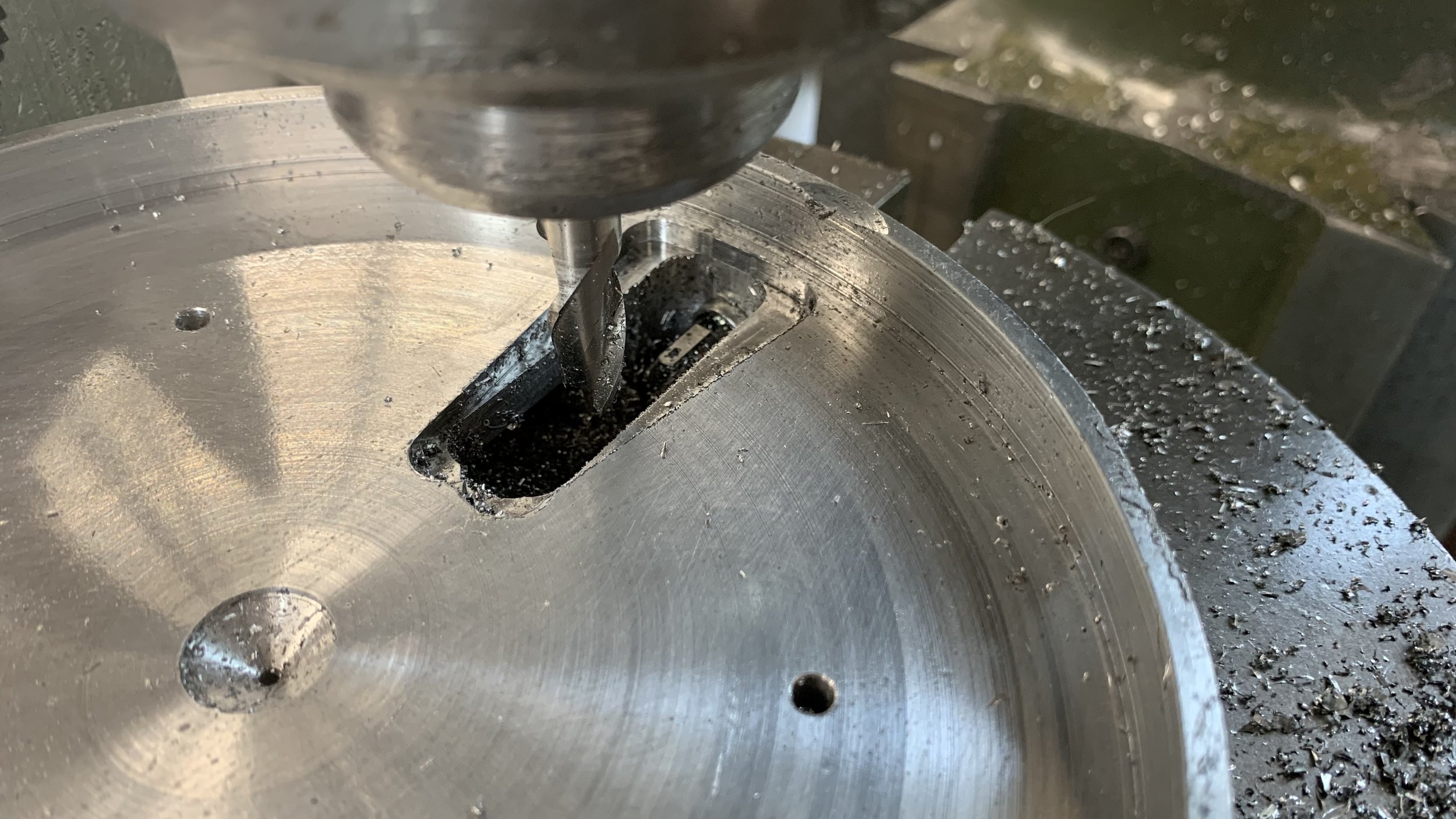
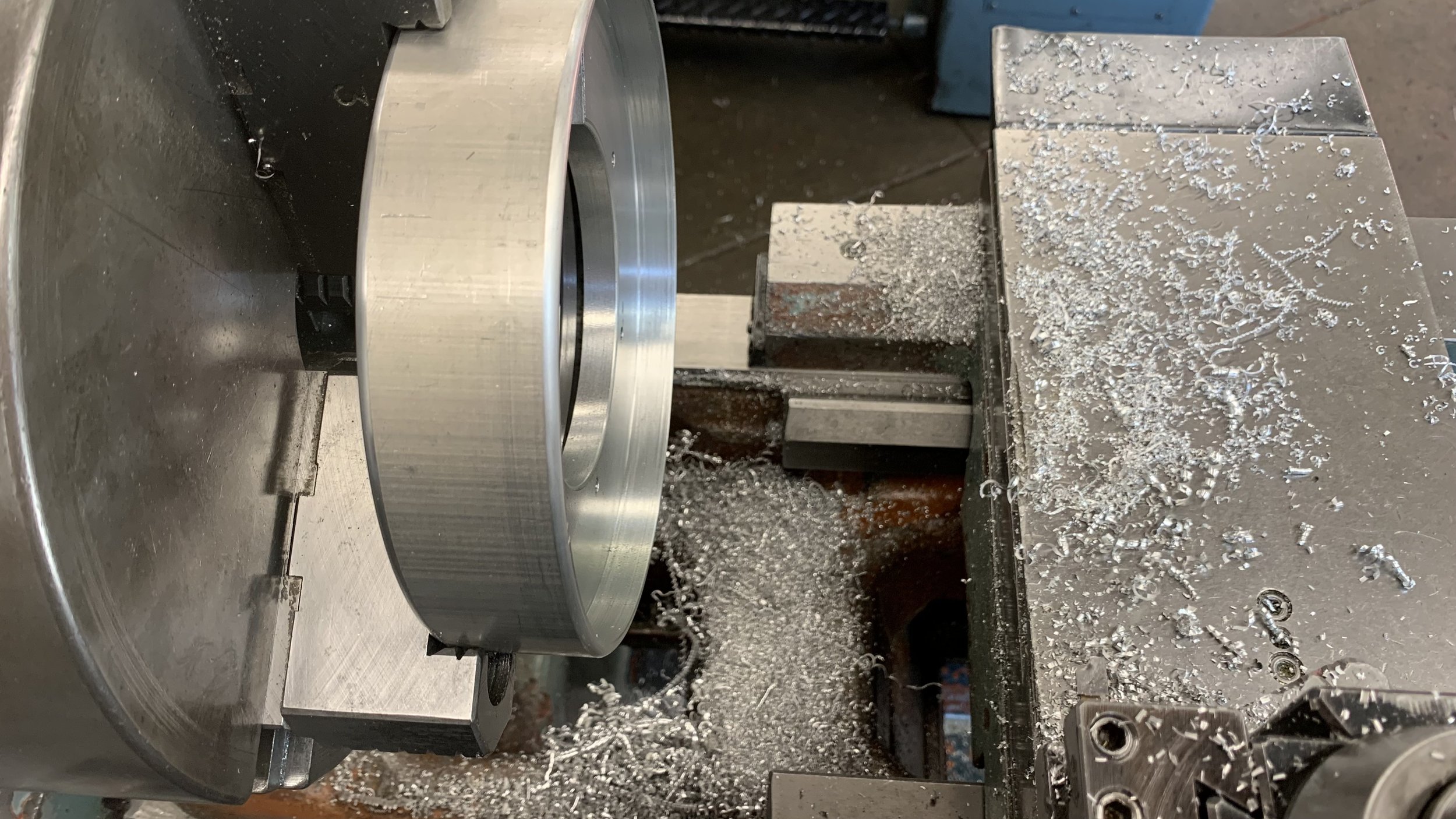
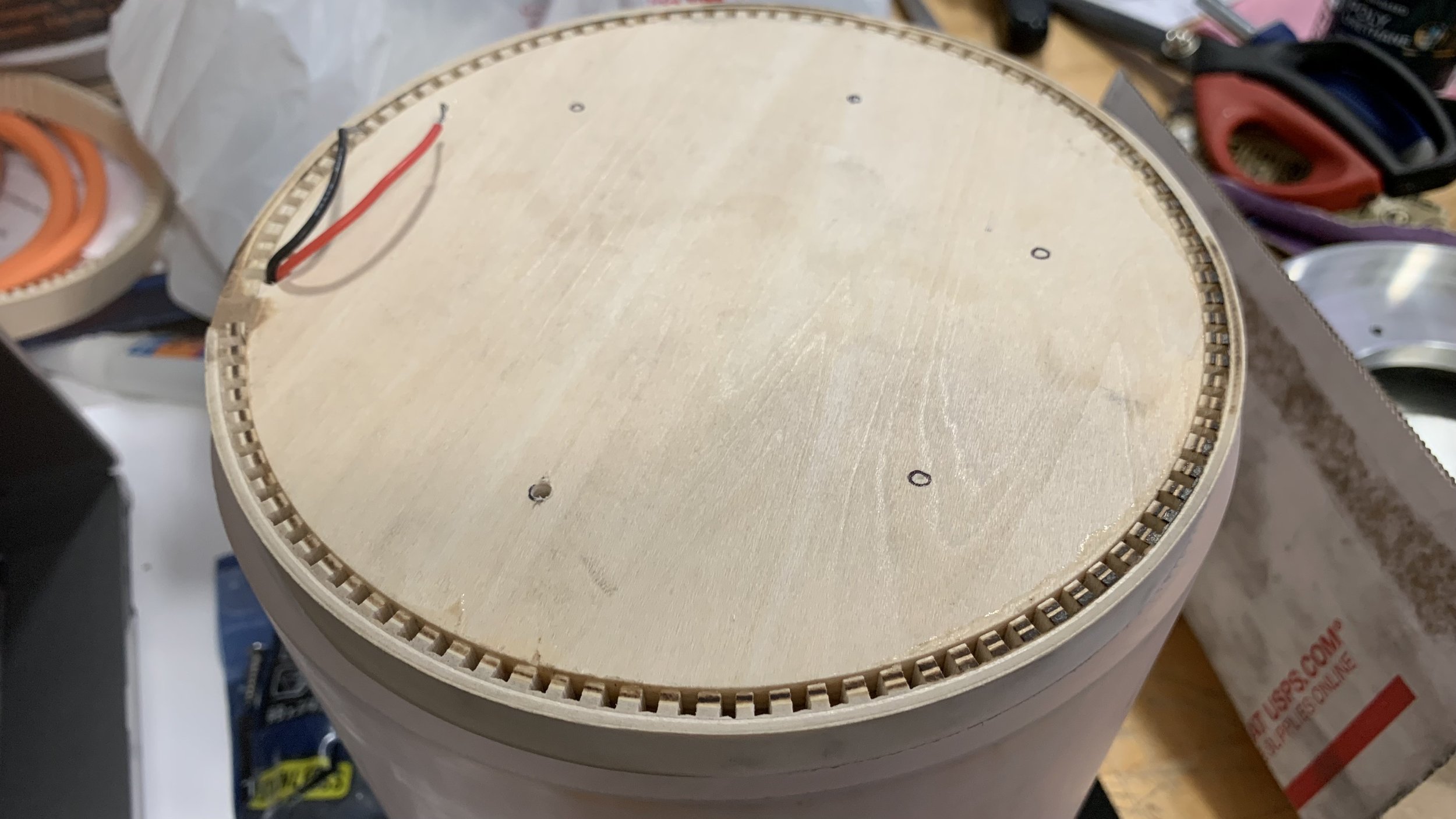
After facing off, a depth was bored out for the bottom metal plate. In order to center the piece on the mill’s rotary table, the center had to be kept and a tiny hole was drilled on the top and bottom side.
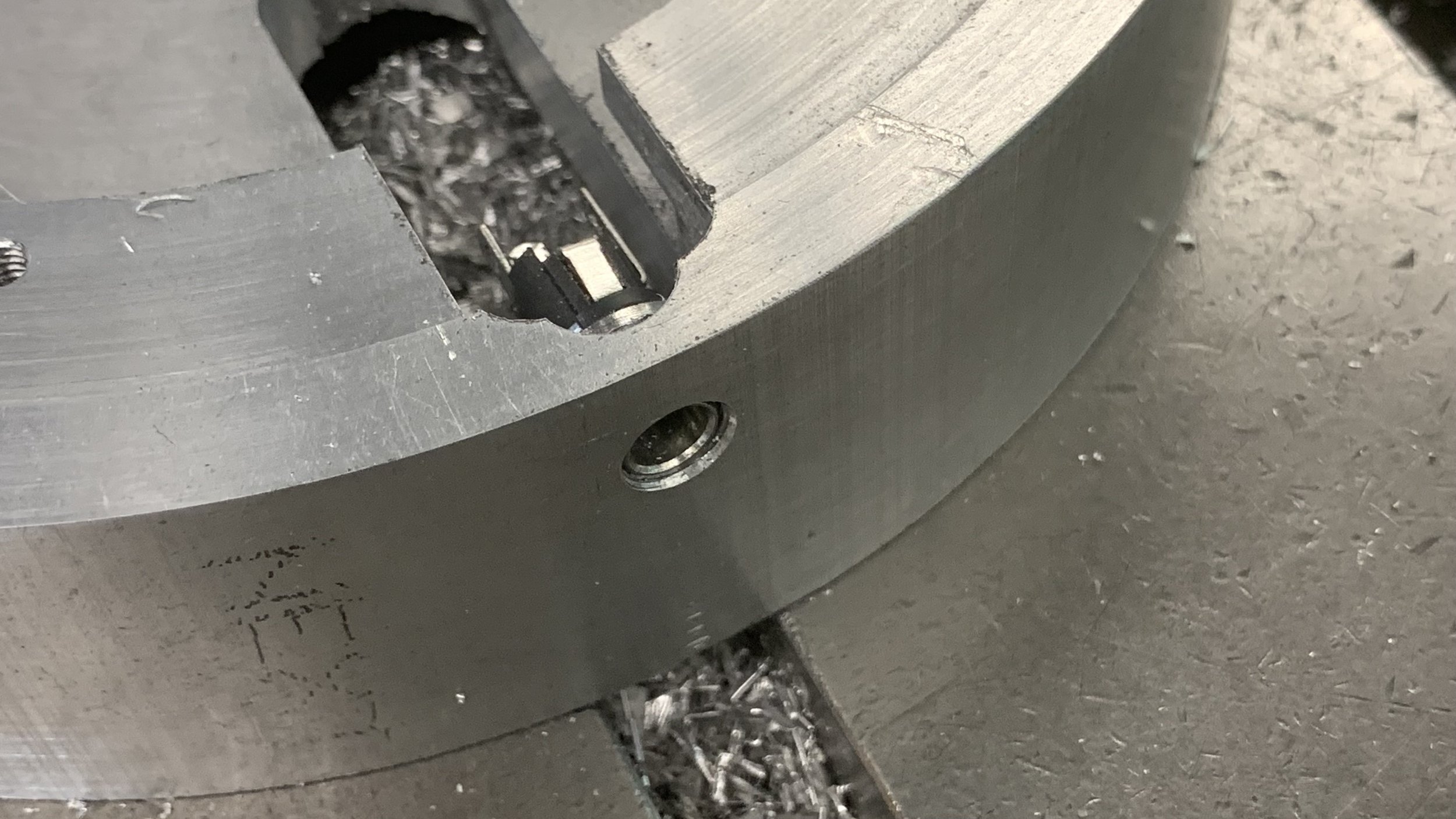
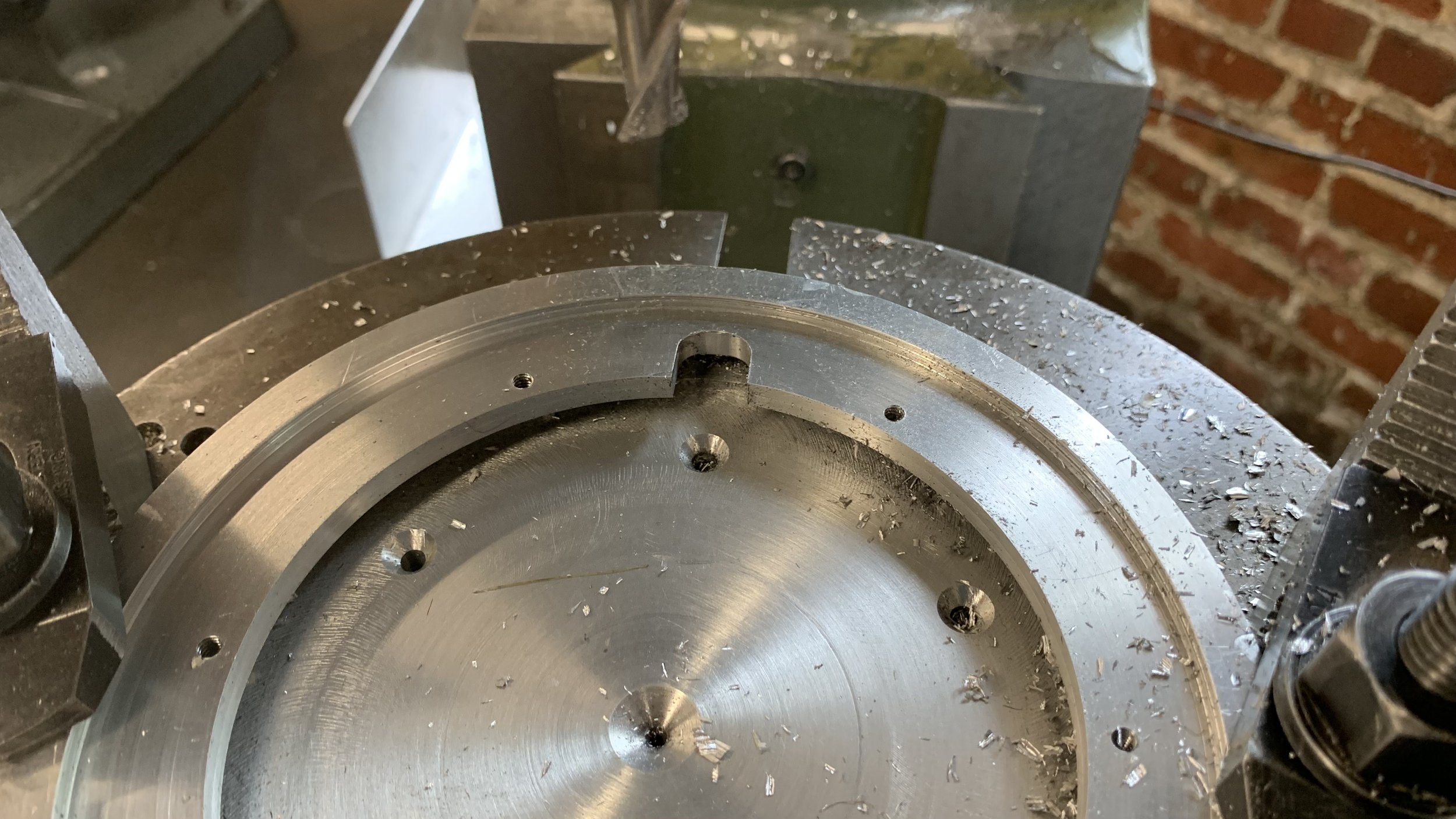
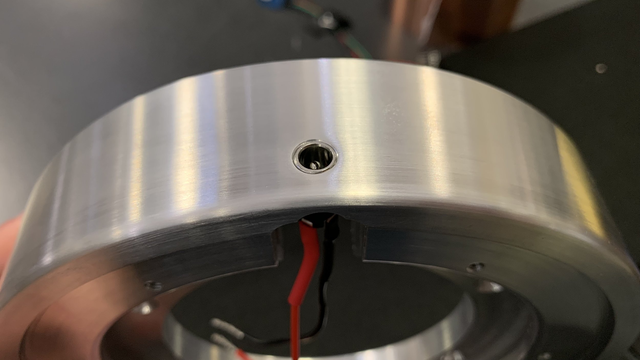
On the rotary table, an internal track was made using a keyway cutter. On the edge of the workpiece, a single tapped hole is chamfered for a female barrel jack to be inserted.
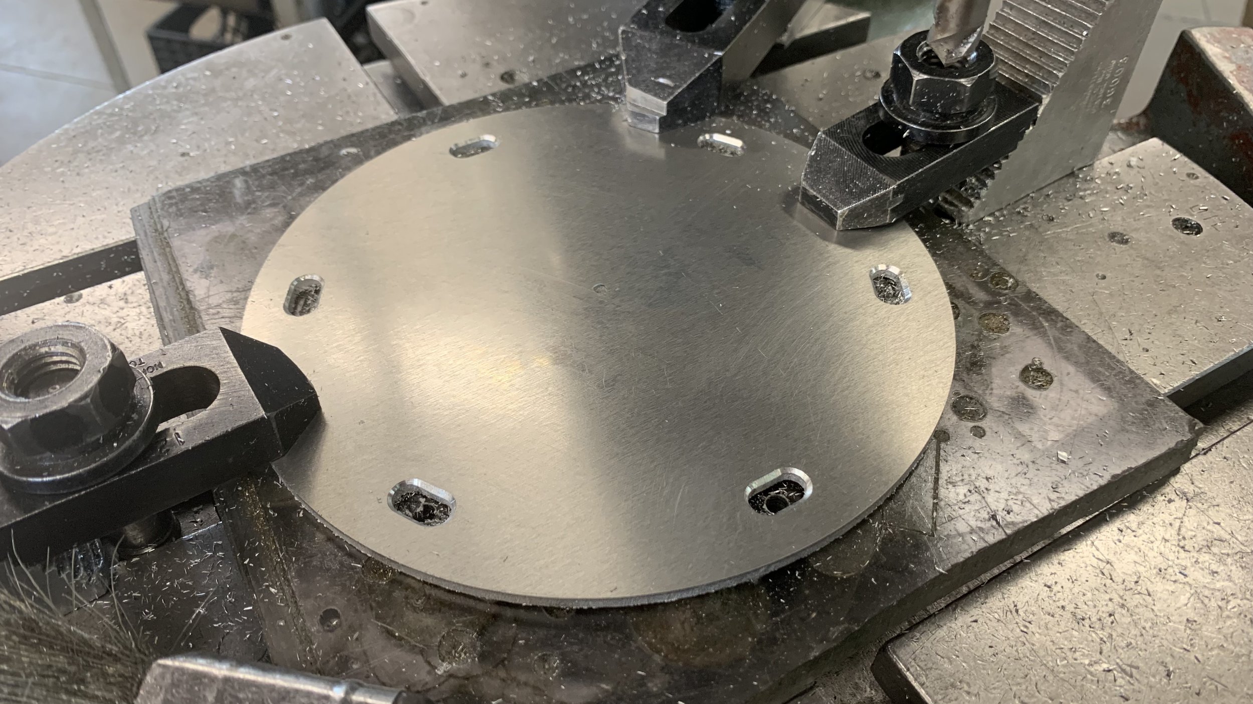
Tapped holes were made for the metal lid as well as clearance holes for the wood base.
The metal lid was made using a laser cutter. A little divot was drawn to allow a finger to lift the lid for easy access. A calculation error was made for the machining of the base, which meant that the base itself already had a spot for a finger. Like my coach said, “this will fit any kind of finger.” :)
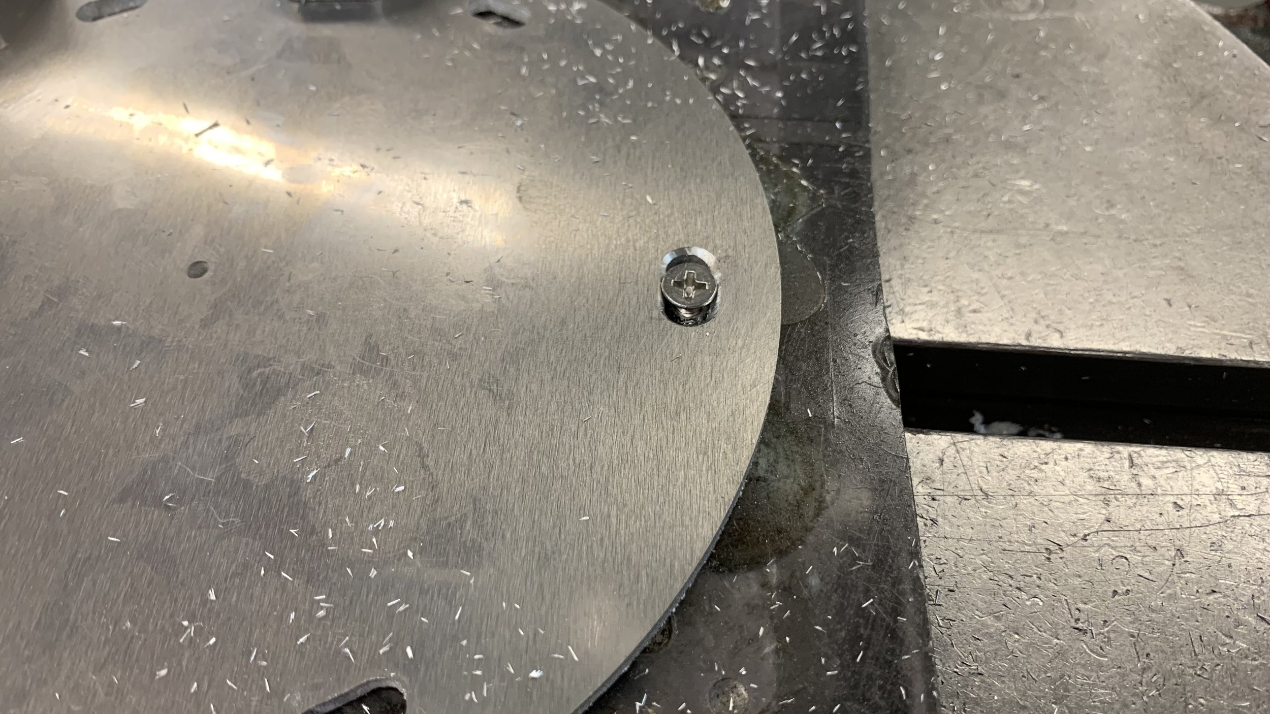
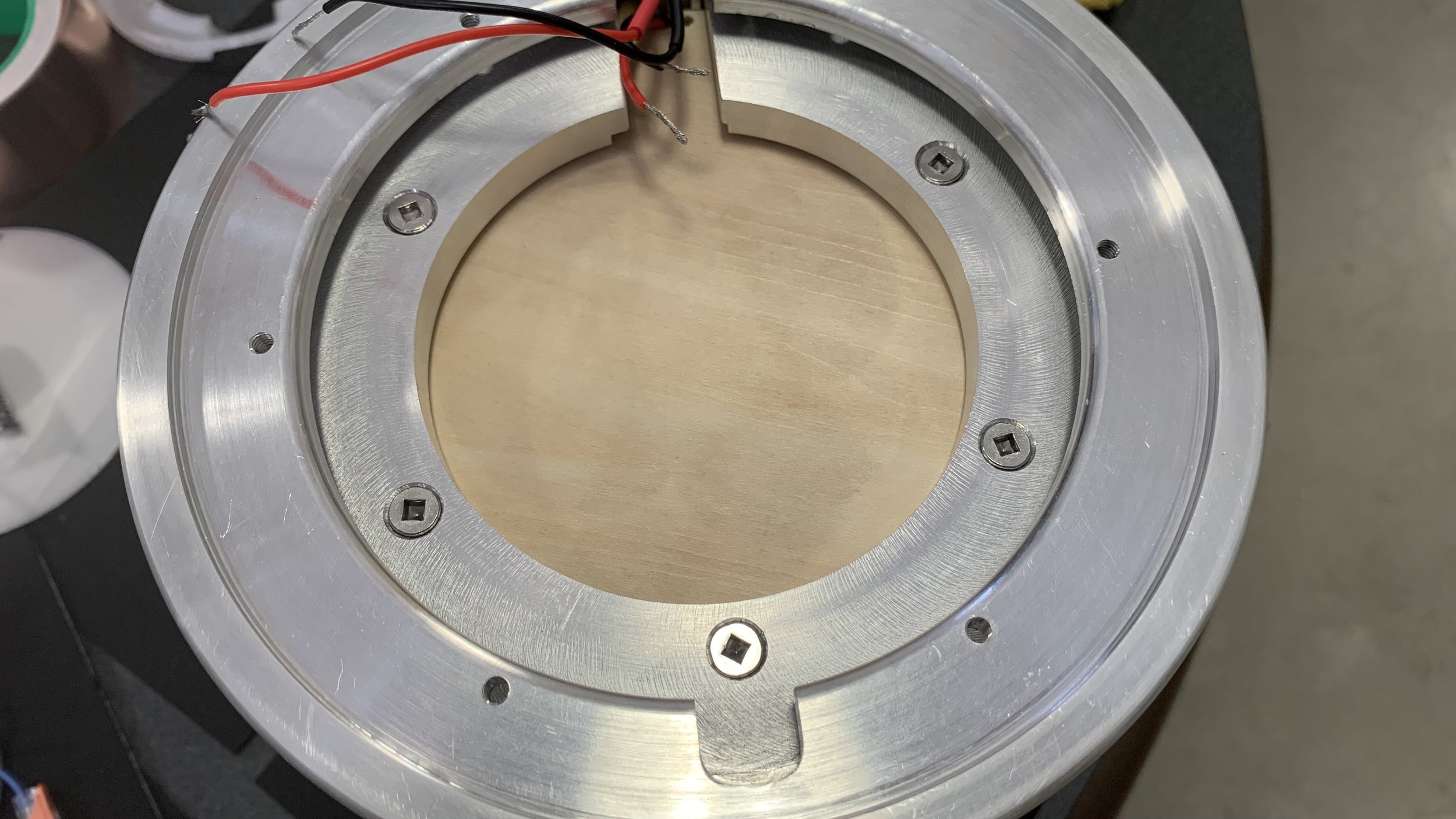
Because the workpiece was centered by eye on the rotary table, it would not be ideal to create clearance holes of the same size. Slots positioned radially will allow for a larger freedom of adjustment.
Laser cutting
Infancy of assembly
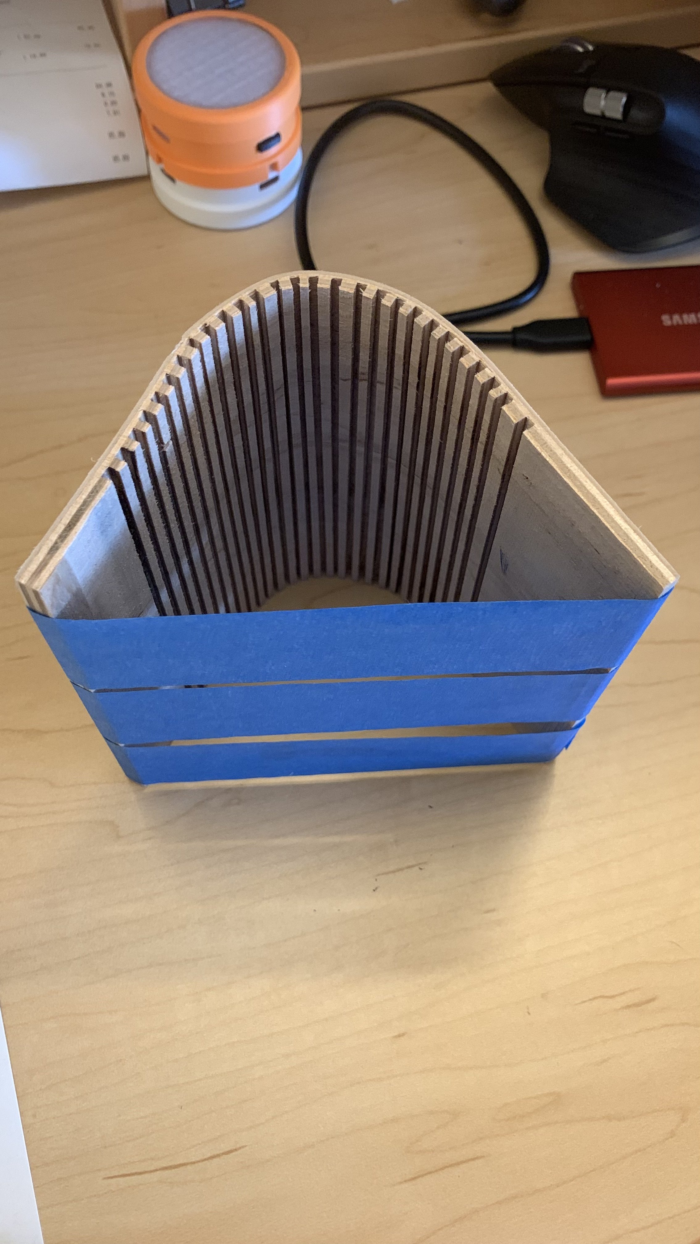
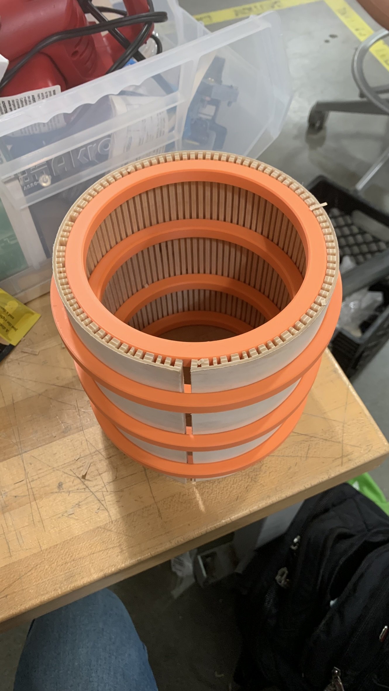
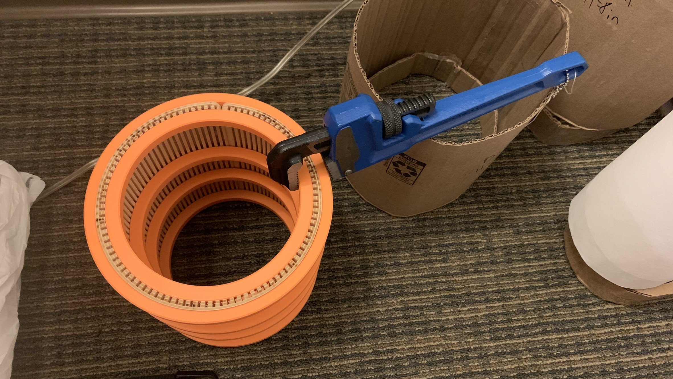
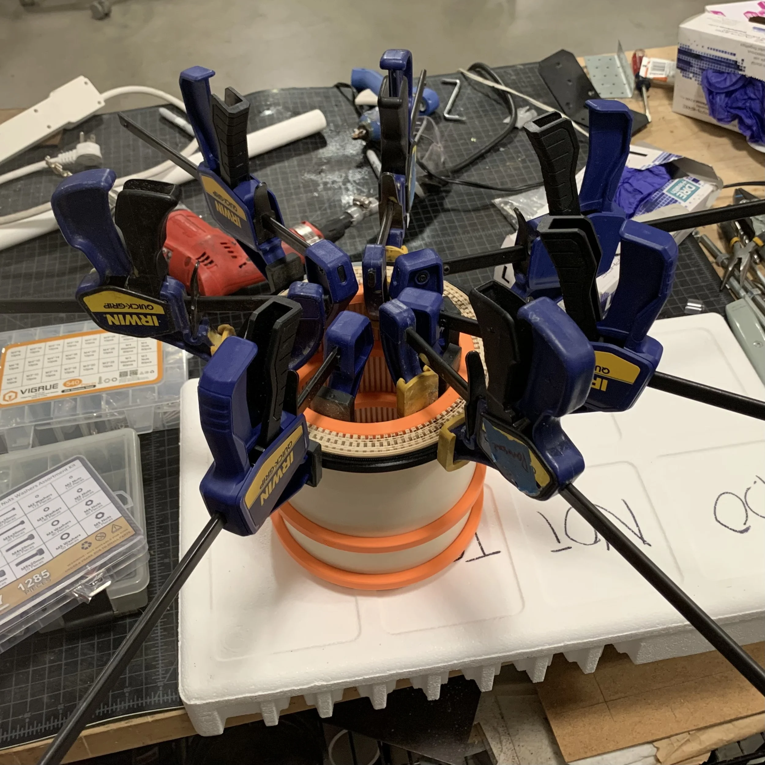
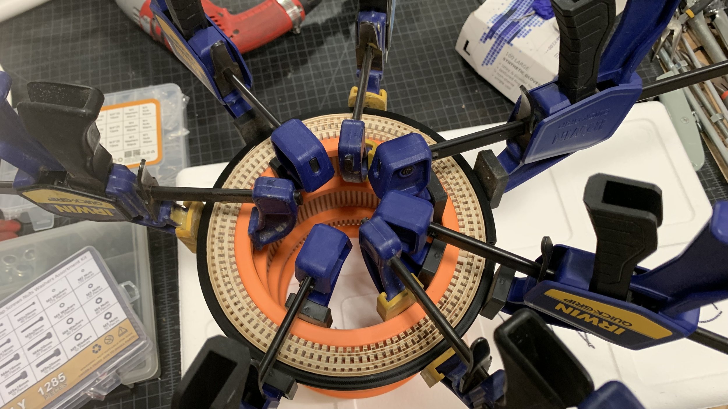
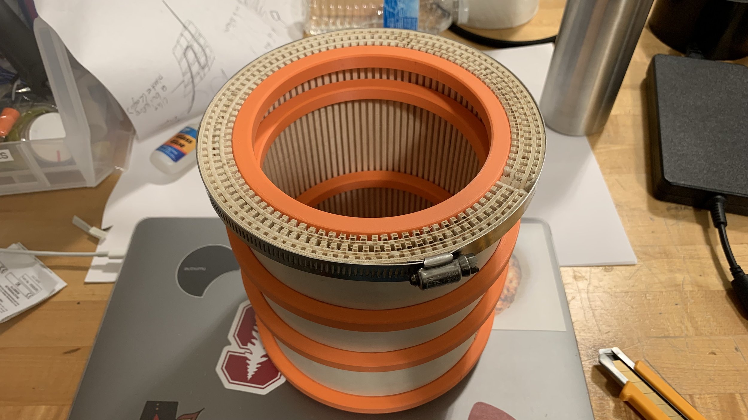
Using the same bain-marie method to bend the rings, the 3rd retaining ring oddly didn’t fit. I biked to the loft in the dead of night where we have a lot more resources and used clamps to hold it in place. However, parts untouched by adjacent clamps started to bulge causing flat spots. I switched to a hose clamp to evenly tighten the ring as they dried. This method was also used to hold the rings in position when gluing.
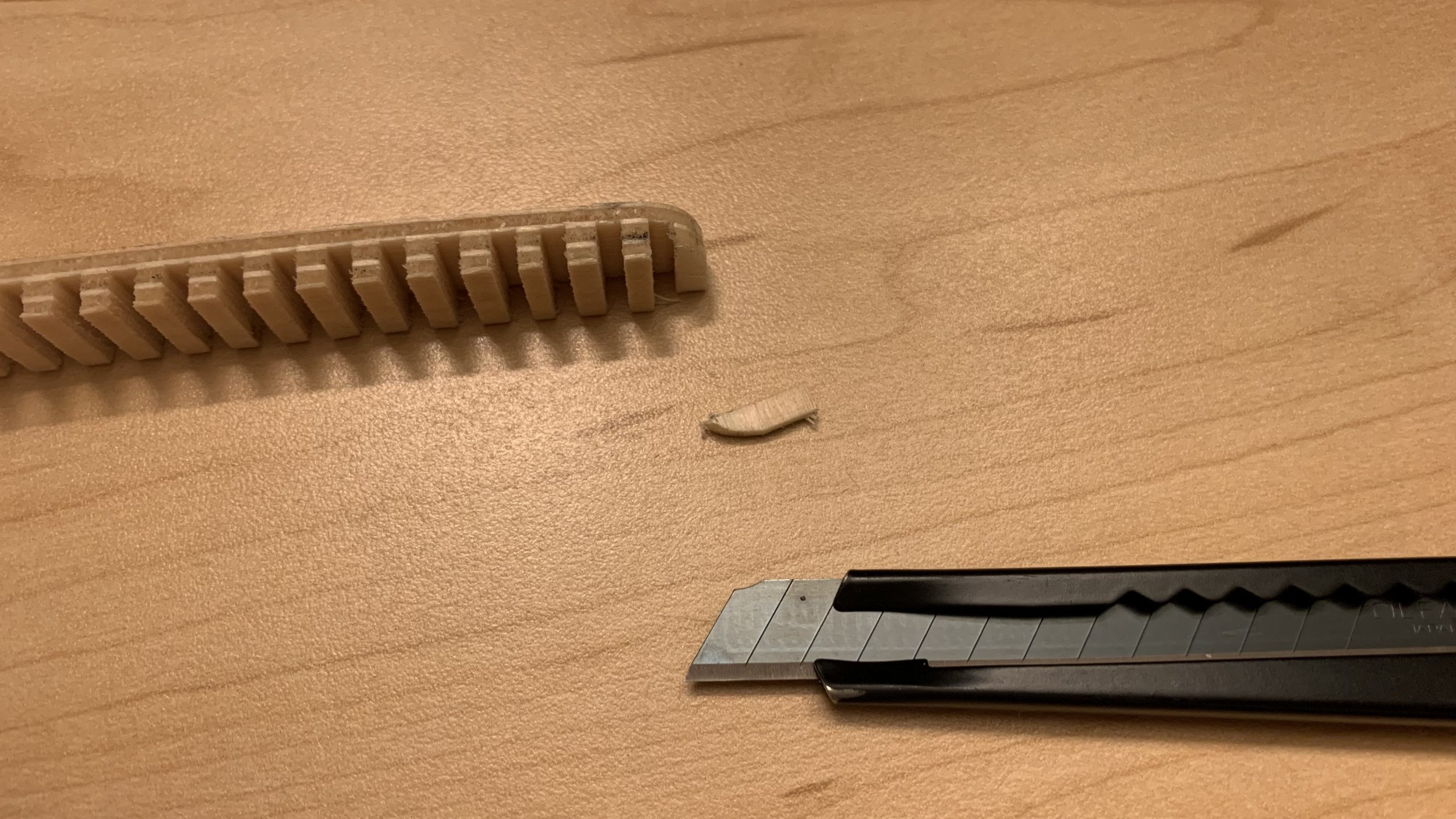
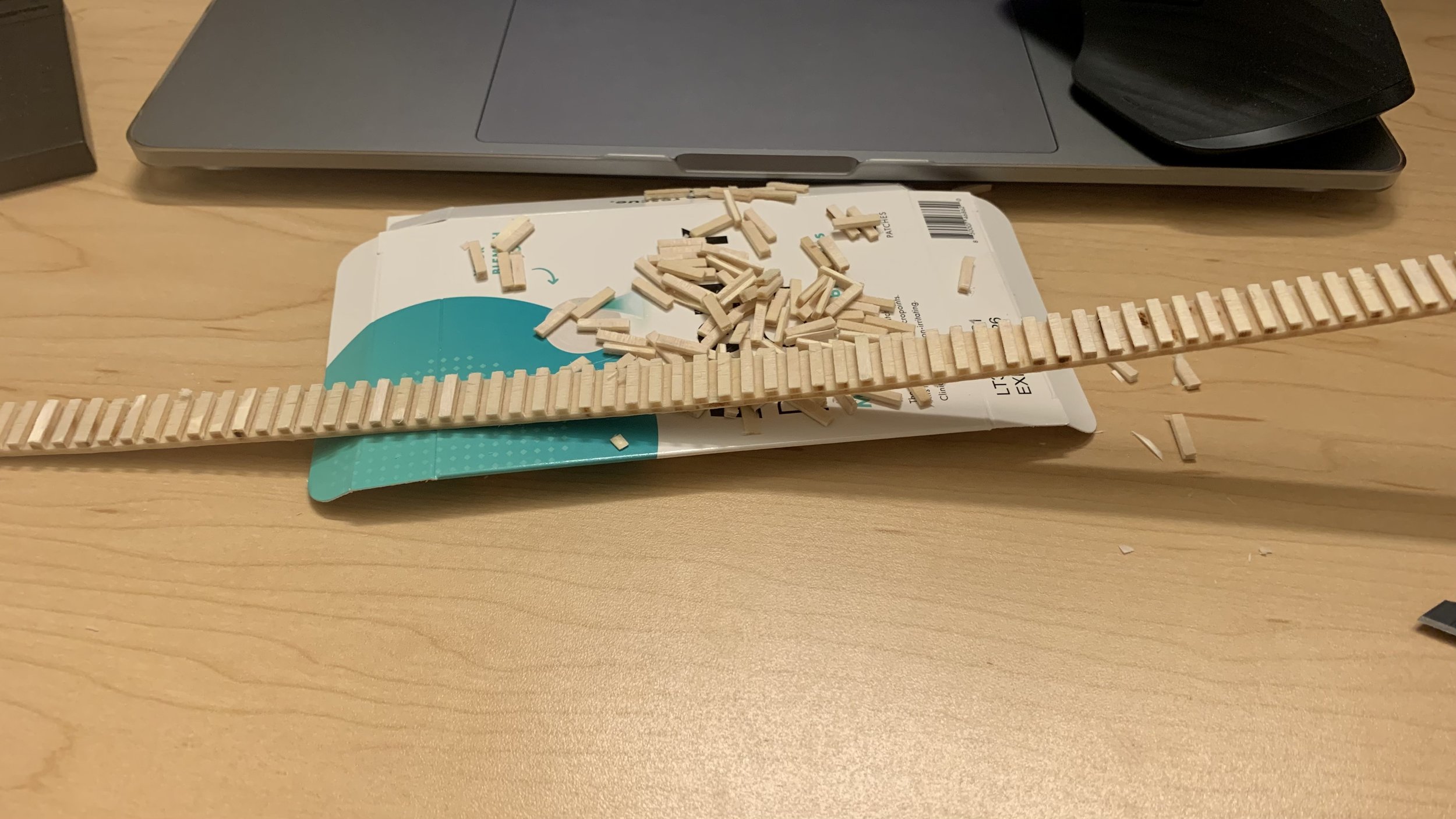
The outermost ring was 1/8” in thickness. The planer in the lab only took sheets down to 1/4” so I had to hand trim over a 100 chips.
The acrylic cylinder unfortunately was 1/10” too big in diameter. I created an alignment tool to make a centered cut. Since it was too tall for a band saw, I scored a line, used a hack saw, and sanded the edge down to size. Due to the cut, it had a tendency to curl in with quite a bit of force. I made a revision to include a ring (luckily had extra) for support.

Final machining
A further slot was cut using a thinner keyway cutter to allow a sensor to sit in. At the back, a slot is milled to allow for barrel jack assembly; channel is milled above it to allow room for wires and prevent them from being pressed between the wood base and aluminum surface.
Countersinks were added to the radial slots on the lid to allow flathead screws to sit flush.
Internal edges had filets added to prevent injury during assembly. Radii were also added to the exterior top and bottom edges.
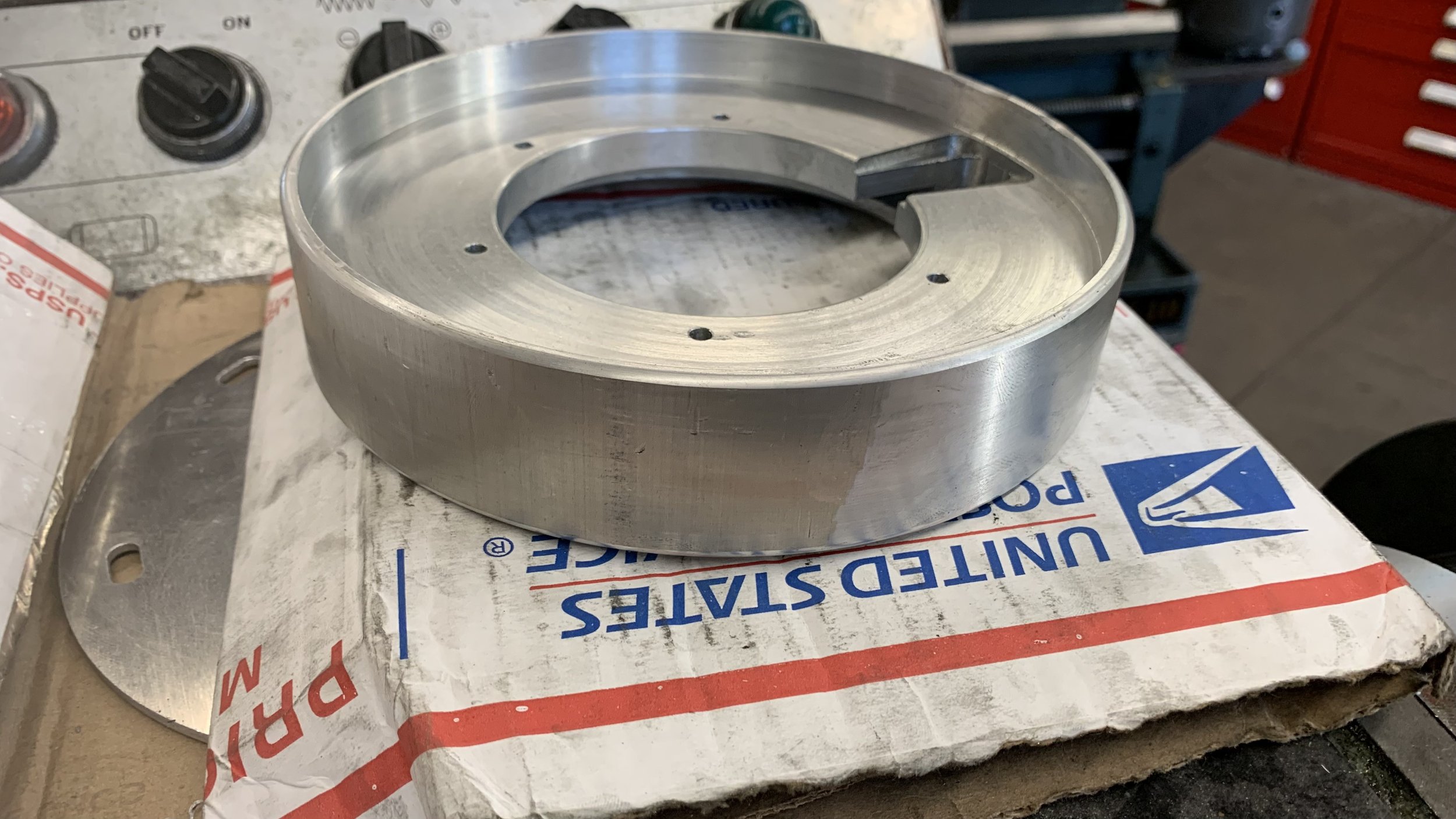
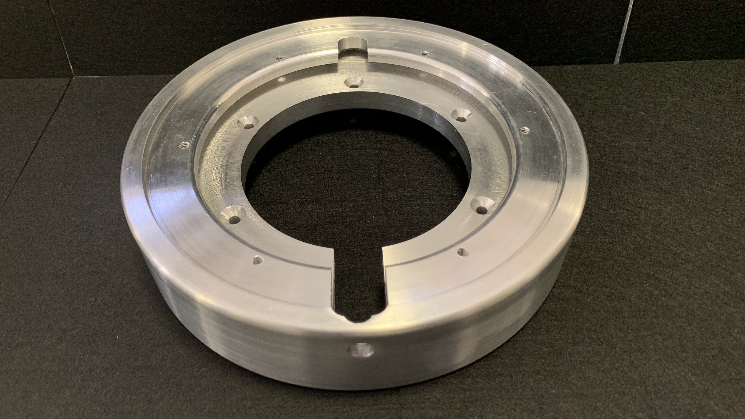
Due to the runout of the stock piece, there was obvious variability when facing off the metal band even when taking off the maximum tolerance. Hand and spot sanding to 800 grit on the lathe was done to remove remaining dings and provide a soft brushed finish.
Sorting the tidbits out
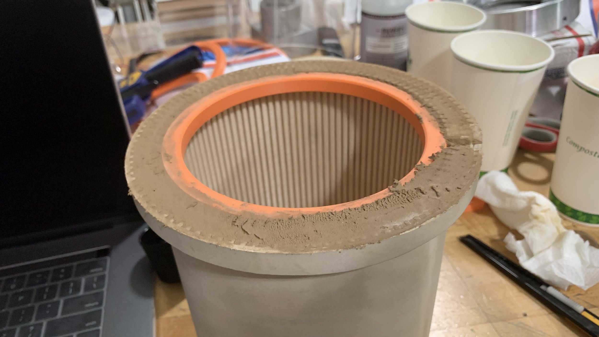
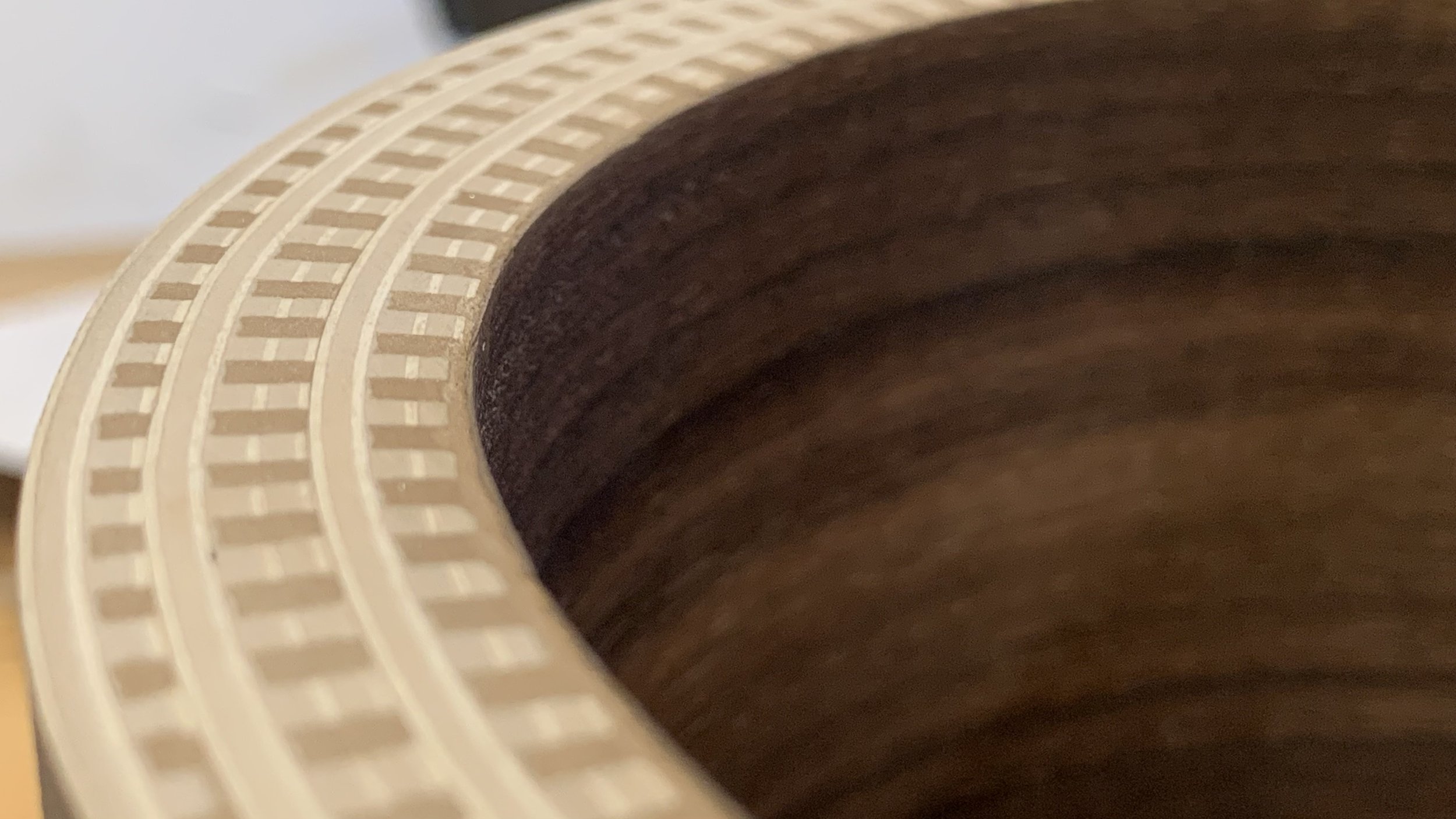
Now that the rings were glued in place, I filled in the kerfs with a contrasting dark walnut wood filler to prevent dust and debris from getting in.
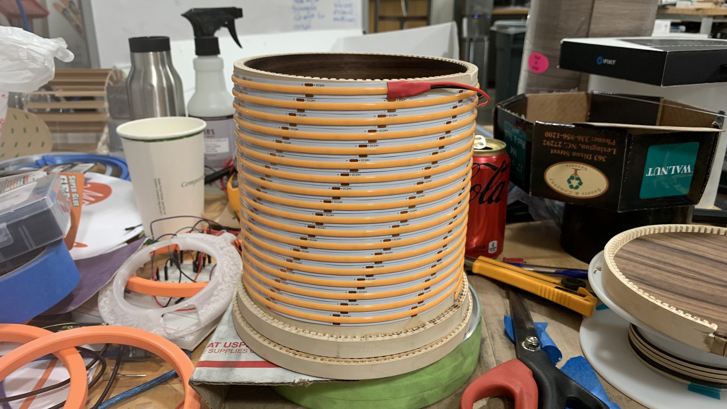
On the electronics side, I began soldering the components together, making sure to test after each connection was made. A 30 ft. LED strip is wrapped around the body and the ends are soldered and fed through the base. Initially, there would be a solder at every end that meets at the seam in the back as the seam wouldn’t be touching. However, two problem arose from that concept: it would introduce a lot more work and shadows of the solder joints would cast onto the veneer. To help with light diffusion, the inside of the acrylic is sanded with 220 grit.
The internal veneer provided quite a bit of trouble. It initially came in a roll, but since the veneer was internal, the rolling had to be reversed. The tendency to curl back made it close to splitting. Because the backing is a strong adhesive, it would grab onto the plywood before everything was in alignment. I used the same oil I used to oil the veneer and added a little to my hand, so I could handle it more easily. Thankfully, the kerfs cuts balanced the difficulty. The nightmare is yet to come.
Nightmare #1
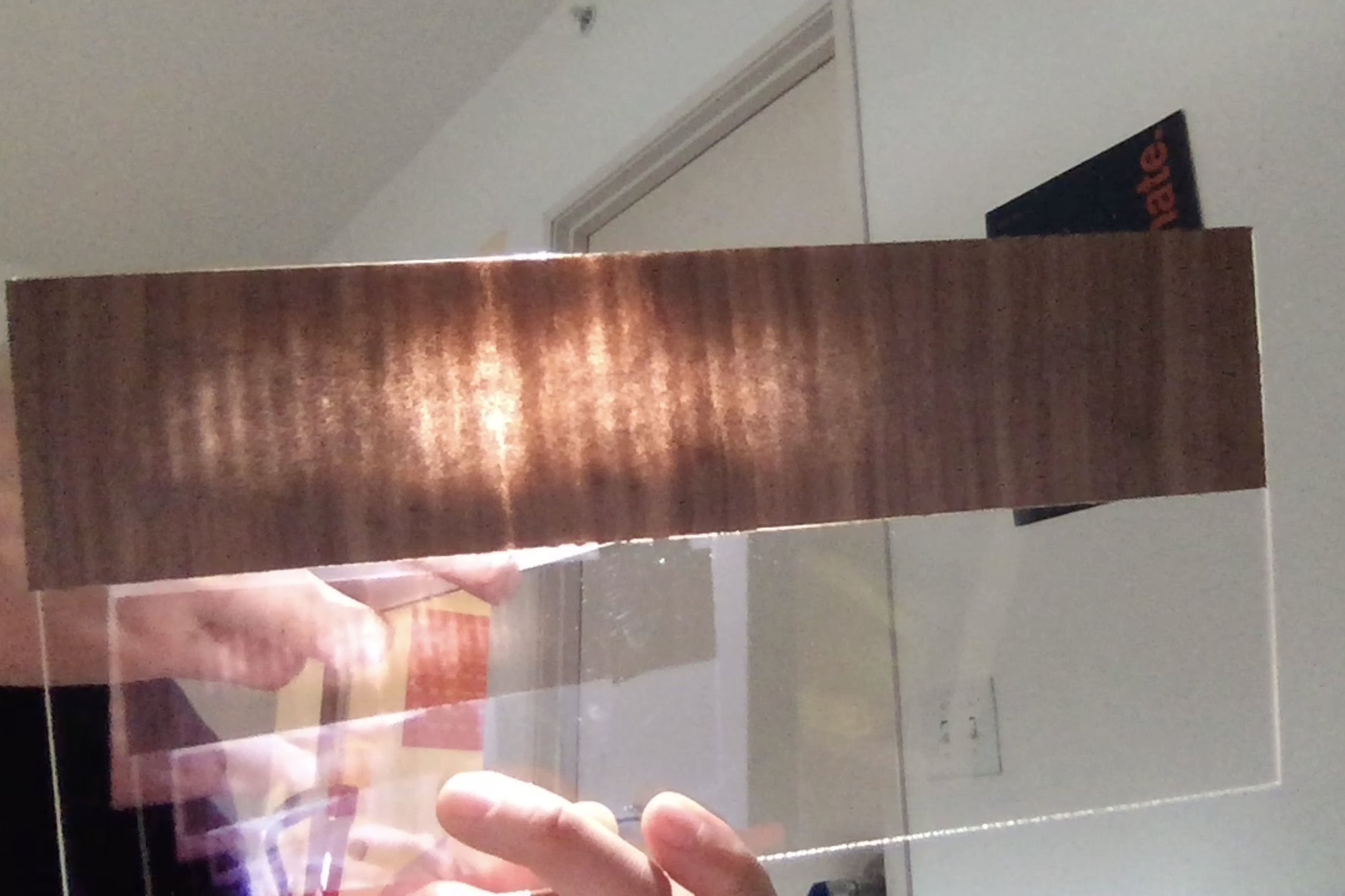
In my test runs on 4 test strips of trying to create translucent veneer by sanding, they were all sanded too far down, which broke the grain structure and showed the adhesive backing. There was a lot of variability: number of passes, grit used, pressure applied. I tried to remedy by using chalk, sponge, sanding block, and a variety of grit levels. Unfortunately, my efforts only yielded a small successful 1 in. × 2 in. section. An 8% success rate.
I had two 4 hour shop sessions left. This time, I needed a 7 in. × 22 in. sheet. Unlike my test runs where I had the privilege of sticking onto a piece of acrylic and checking with a flashlight, the backing had to stay on as it’s on a sanding table. I would also have to balance the number of times I checked as taking off the tape, peeling a bit of the backing, shining my flashlight, and putting on new painter’s tape costed precious time.
I realized chalk to be pointless around 2 hours in. I used 180 grit sandpaper, relied only on the weight of the orbiter sander for pressure, and zoned away for the remaining 6 hours.
This was the pièce de résistance, the make or break of my entire project. And I wouldn’t know how it turned out until it’s stuck on the acrylic. It was a tremendous gamble.
Nightmare #2
It was time to put the veneer on. I trimmed it to size as the sanding piece had a 2 in. offset around the perimeter. I peeled the giant backing off and aligned the edge with the edge of the plywood. As it pressed along the way, a small shift in alignment caused the veneer to angle and spiral upwards. I started to remove it, but the section initially applied was really stuck onto the acrylic. Unlike the kerf cut plywood, the smooth acrylic was absolutely unforgiving.
I was extremely stressed. How could it all come down to this? My calming tactics were definitely at war with my emotions, but I didn’t let the latter get the best of me.
A utility knife in one hand and a scary amount of prying force in the other, I slowly cut the adhesive while intermittently using a heat gun to soften it. Since the veneer was even thinner than before, I truly thought it was going to rip at any moment.
At last, it peeled off, but at the price of wrinkles and a ruined and less tacky adhesive. Super glue was not an option as the marks will show. It was a very depressing moment.
But I remembered that heat is what made my plywood bend. This time, I positioned the lamp upside down so all the edges met at the flat surface of the table and took care not to apply too much pressure in case it needed realignment. Once the alignment was correct, I used the heat gun to hopefully soften the adhesive and allow it to stick again. Miraculously, it ironed out the wrinkles and the adhesive stuck back on like new.
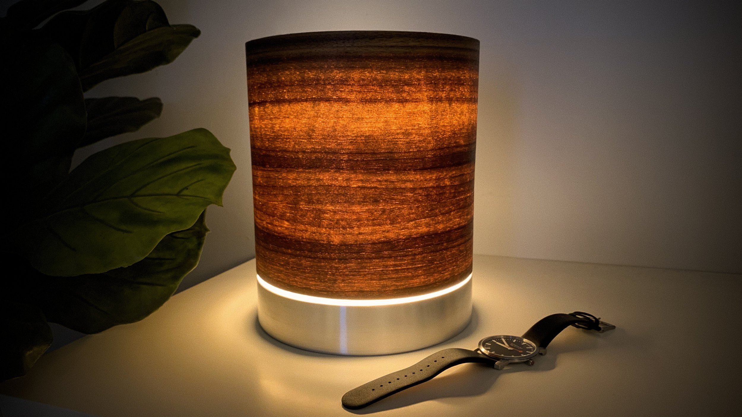
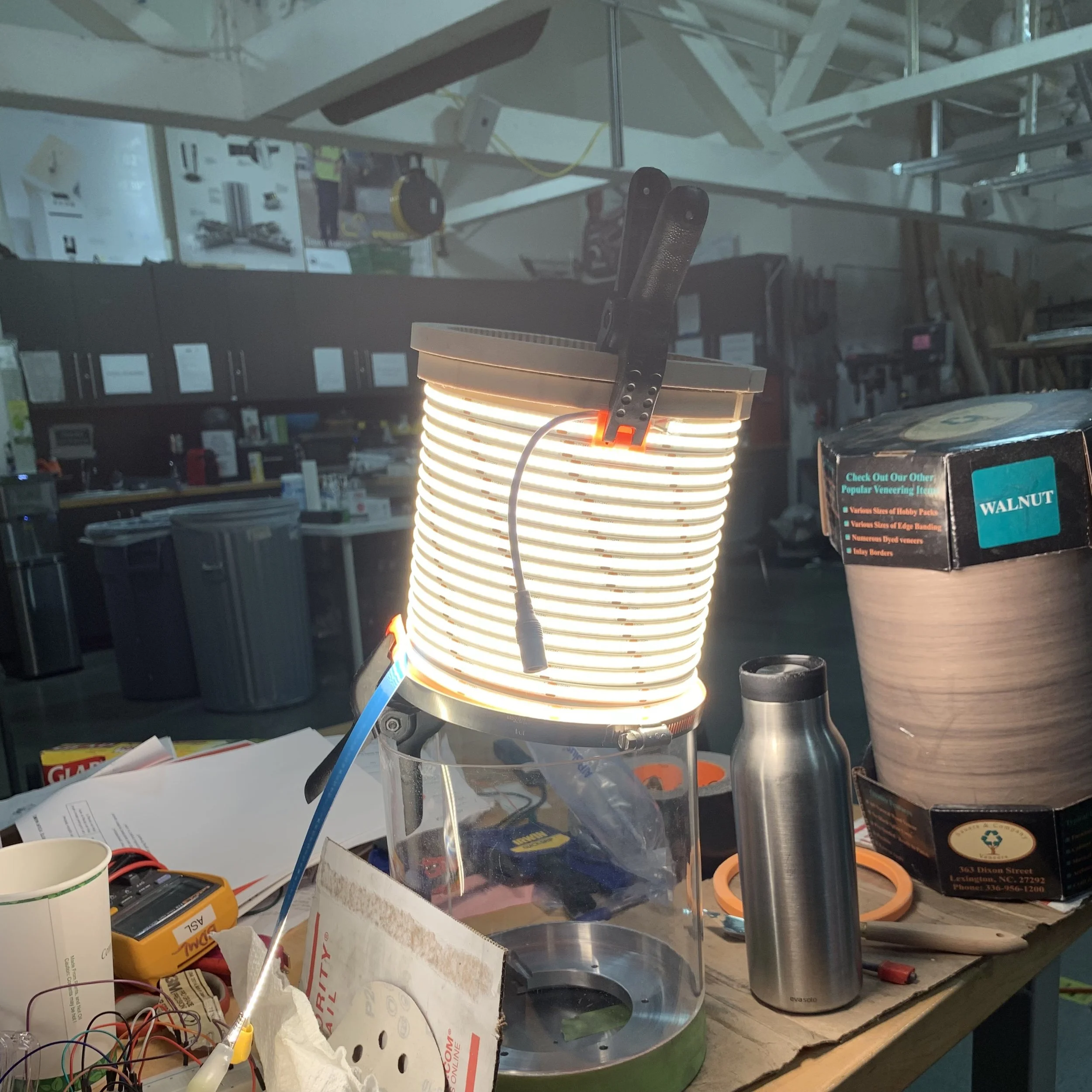
Moment of appreciation
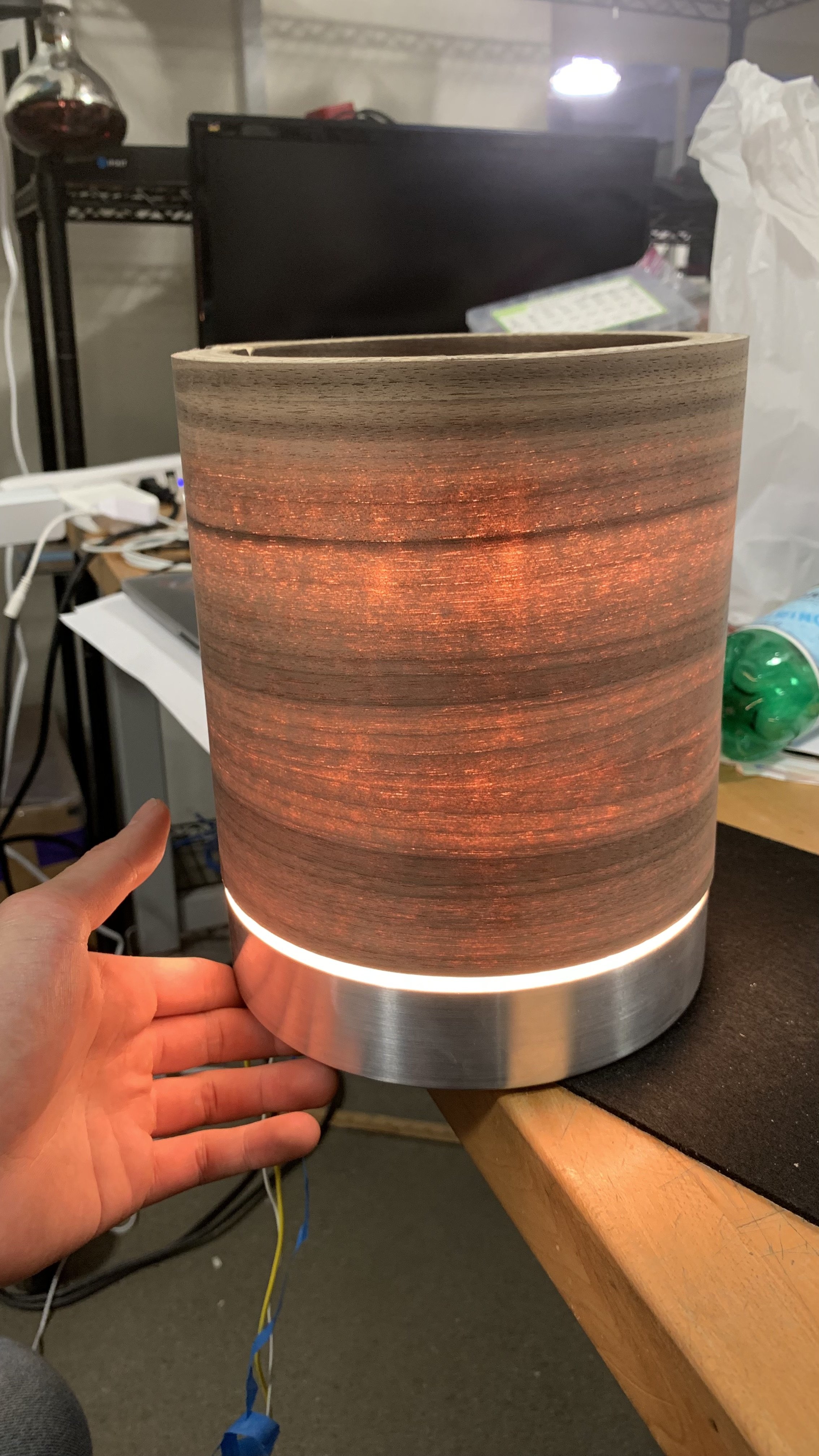
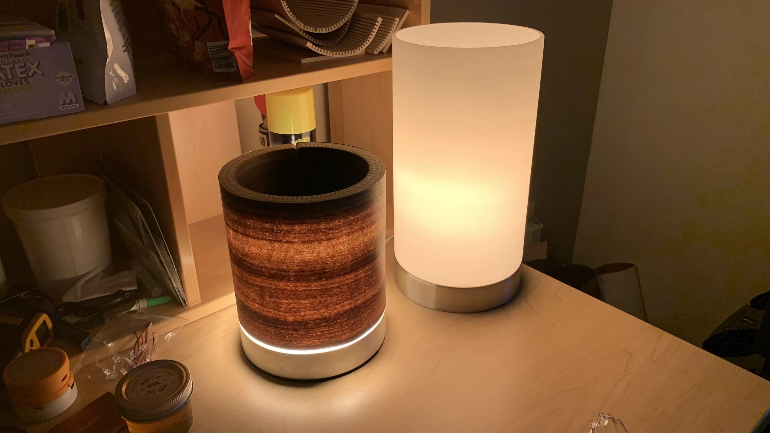
Below is a little breather.
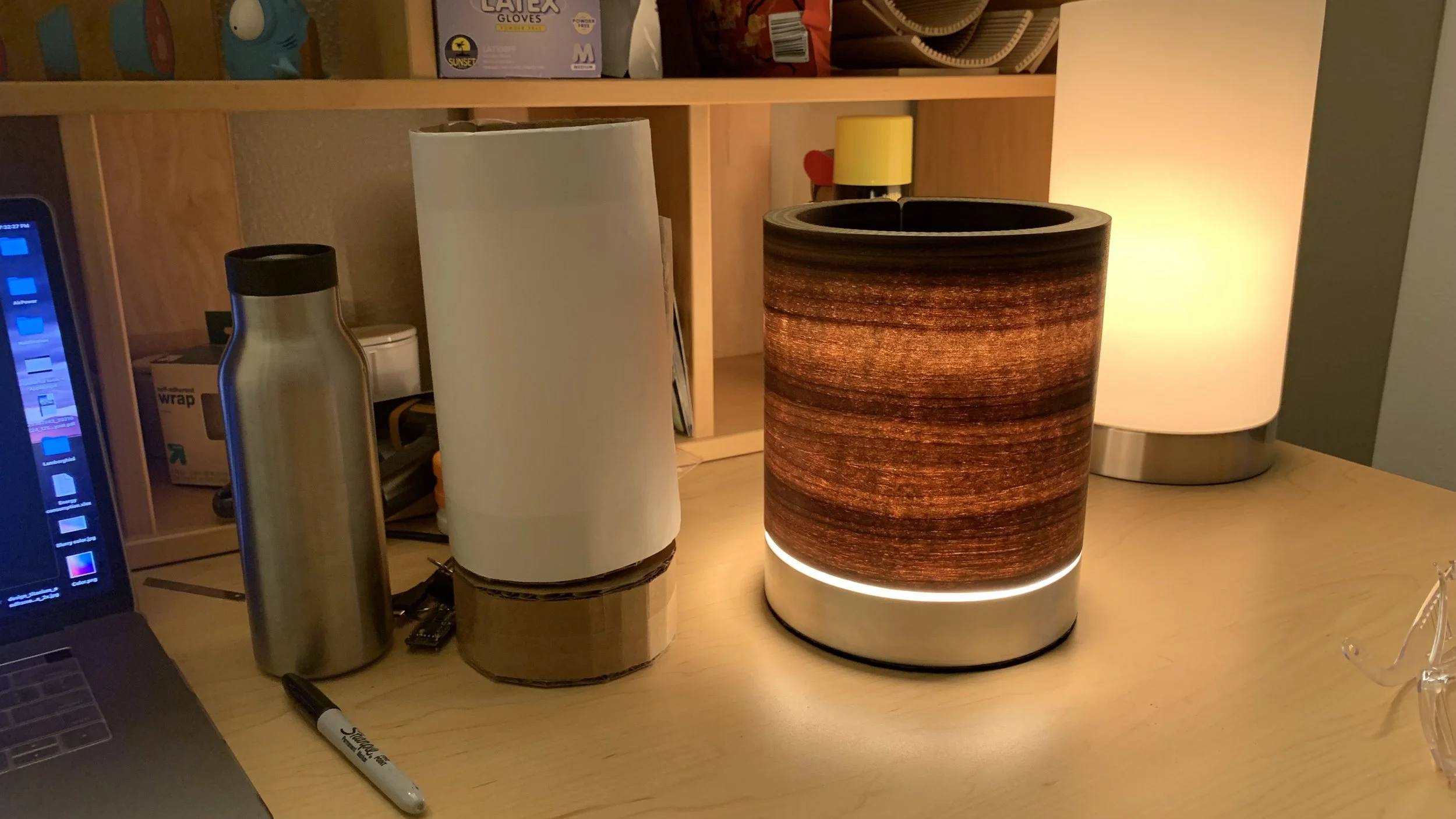
It shows the first moment I turned on the lamp to see if the veneer worked.
It shows the beautiful walnut fill contrasting with the hundreds of kerf cuts.
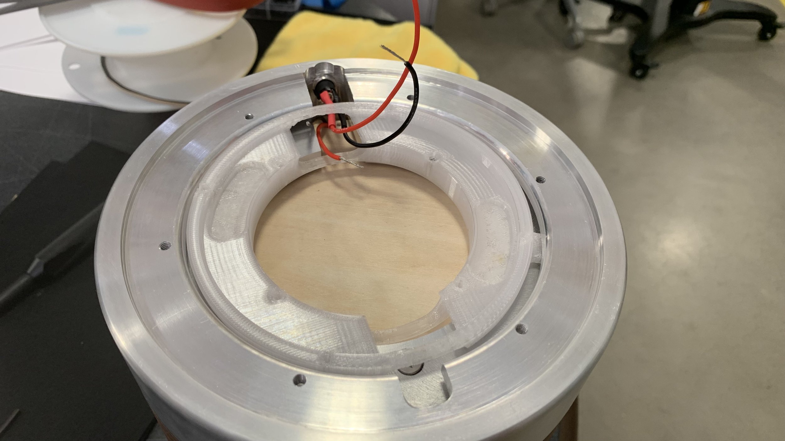
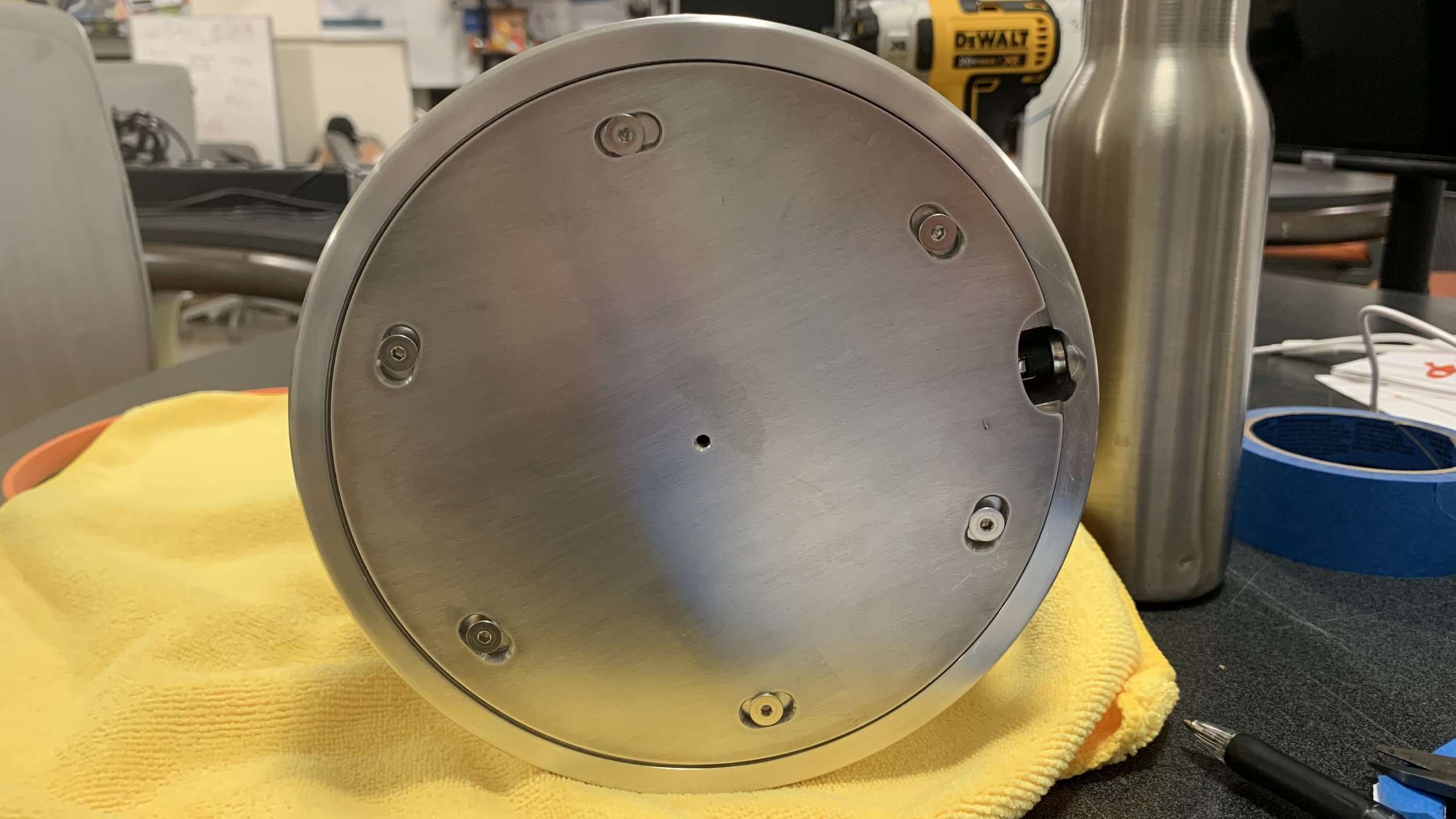
It shows the complexity of the internal base to provide the simplicity of a brushed finish aluminum band.
The blood & sweat (literally) and restless hours I poured into this is beyond anything I’ve done.
Final assembly hiccups
It was time for assembly. The female barrel jack sat flush with the aluminum band with a small countersink to give the edge a tiny sparkle.
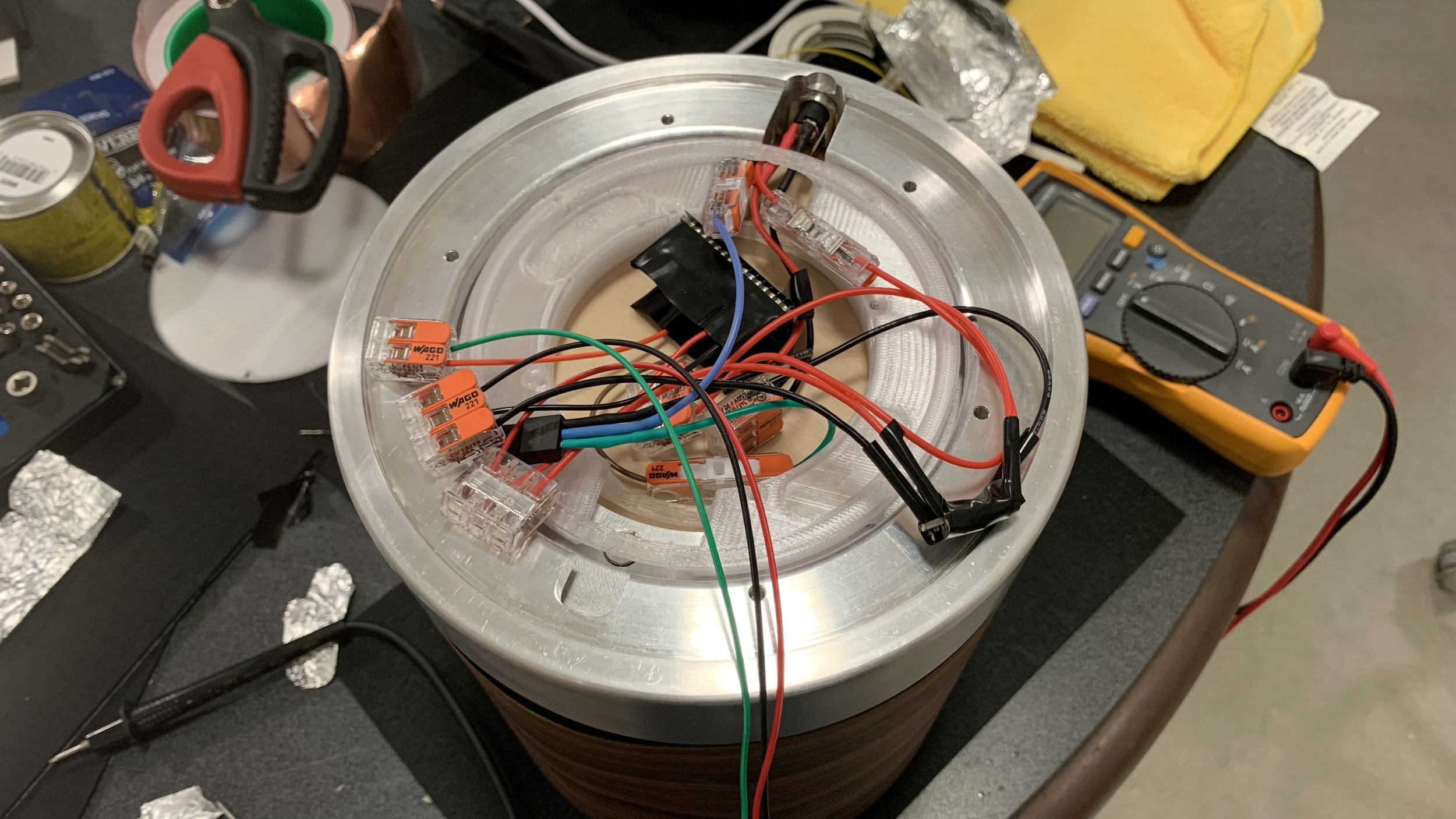
To prevent any shorting incidents, electronics were all contained in a nonconductive housing. Everything looked uphill from here on out. Lo and behold, an electrifying fiasco occurs. For some reason, the touch sensor didn’t work when attached to the aluminum base. The lights would toggle when the sensor touched the metal, but when they’re intertwined and a user touches the metal, nothing happens. It worked during testing when I wrapped a piece of foil over the sensor and had the metal touch the foil. I tried foil tape, copper tape, and back to regular foil, but none worked. When I recreated the scenario with a giant piece of foil, it worked oddly enough. Upon testing voltage between components, the lead accidentally touched an onboard element and my fully soldered system fried.
I quickly rebuilt the system using WAGO connectors to ensure it wasn’t a shoddy soldering job. T he same error persisted. However, when I had the touch sensor resting against the metal, then restart the Arduino, it worked. I tested this by leaving them touching, unplugging the barrel jack, and replugging it in. That somehow shorted my last remaining touch sensor.
I had no choice but to wire the jack directly to the LED strip and bypass the circuit for the presentation. It was already 4am and the presentation starts at 8. I’ll fix it in post.
End of a journey
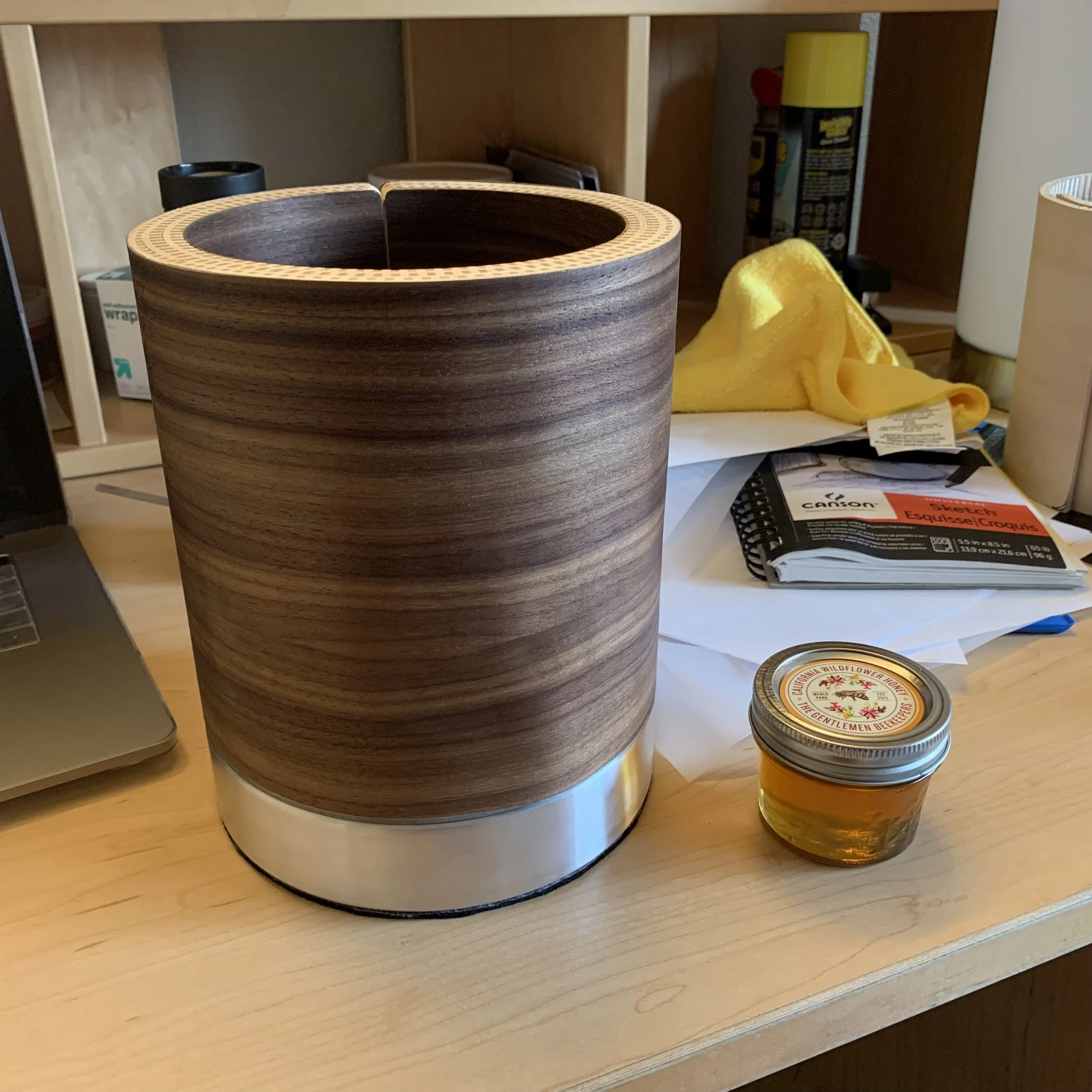
After assembly, I initially wanted to use a water-based satin polyurethane (according to the representative when I asked about matching the coating on the Eames Lounge chair) for the veneer but applying that on the test strip did not yield the deep rich walnut color I wanted, so I used some natural olive oil. I later learned that olive oil can turn rancid, so I stripped it and applied wood honey. The top edge was given two coats of the satin polyurethane coating instead. The base was given a wipe to remove fingerprints.
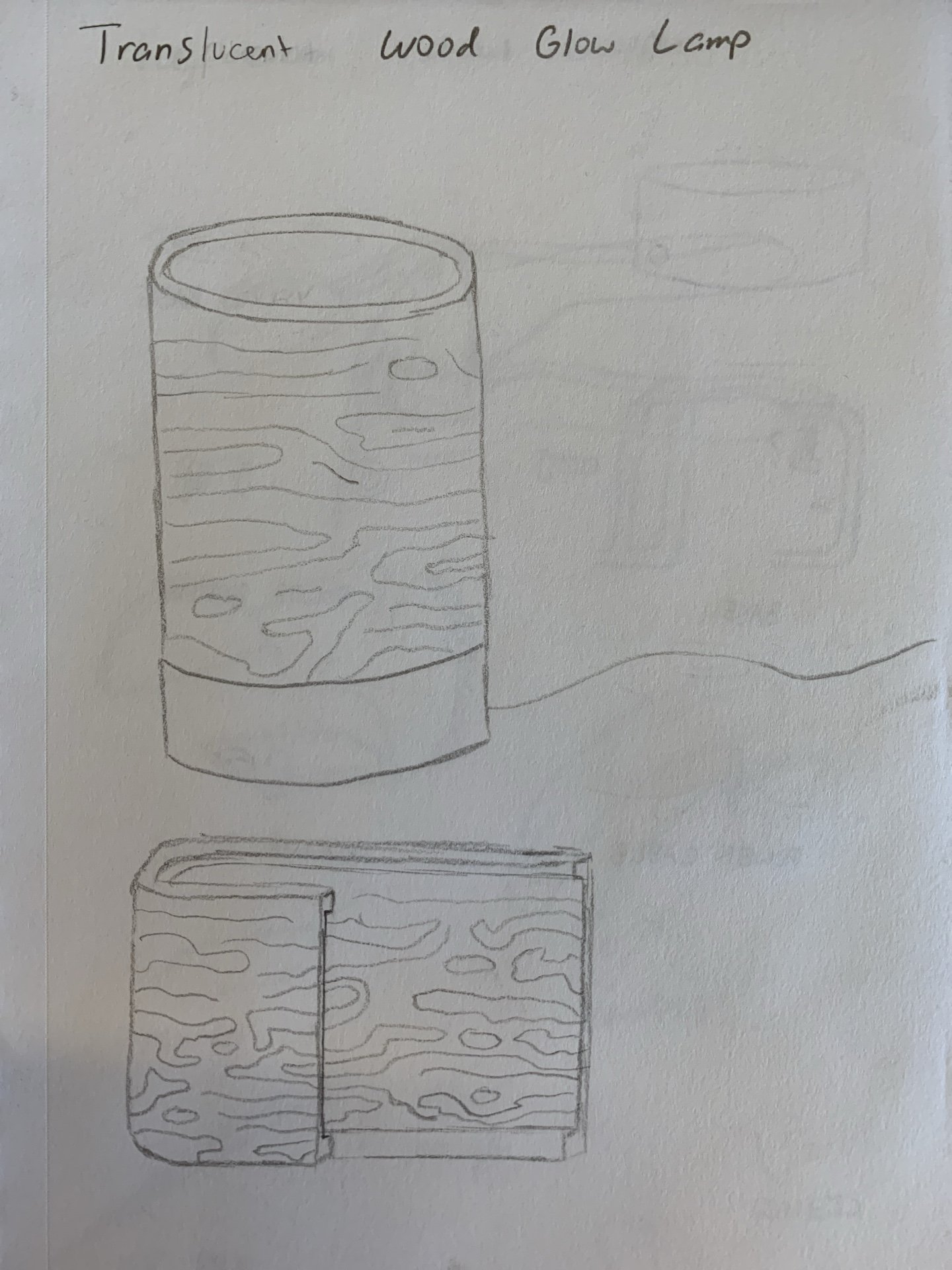
From the inspiration of the frosted glass glow lamp to the quick prototype made from paper and cardboard, it was incredible to set them side by side.
Nothing left except to power it on.
Gratitude
I have so many people to thank, but the trumpet will probably get too loud, so I’ll make it short.
Andy — for offering what is my favorite class ever and showing me such intriguing processes in the world of manufacturing.
Rachel — my awesome coach who convinced me to take on this idea even though I thought I wasn’t going to yield.
PRL CAs — no one ever shied away from helping me or answering my questions. Michael especially for helping me the most with my efforts.
William — who offered help with my circuitry struggles during busy times.
Elle — who offered me assurance during my darkest and most stressful moment.
I have made something I’m truly proud of.